By John de Jong
|
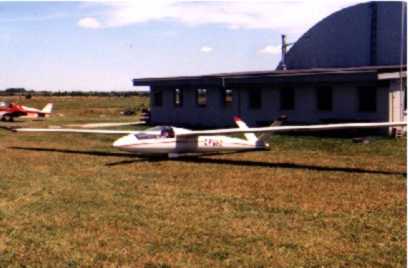
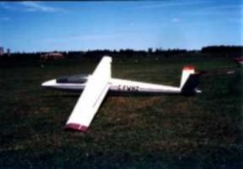
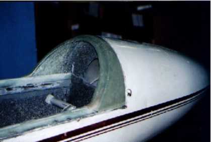
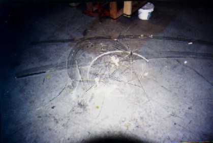
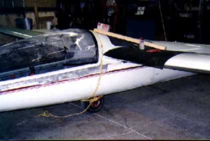
Spring 1996: When Alex Upchurch and I bought our HP14 CF-WHZ, one of the things that concerned us was the canopy. It was a very unusual shape, and made of very thin plastic that you could actually deform by pushing on is (to the tune of 1/4" and more deflections with approx. 5lbs or less of push). As such we decided that replacement of the canopy would be one of our future projects.
Late September 1997: Over the past year we have gotten to know a few of the home builders in the area (Southern Ontario, Canada), and a few decided it is time to make a few canopies. The call went out and one day the group of us (approx. 14 people) formed 2 practice and ~12-14 good canopies.
September 6, 1998: About 10:30 in the evening we get hit by an unexpected thunderstorm accompanied by golf ball sized hail. Nine aircraft are damaged, with our HP being the worse – the canopy had a fist-sized hole in it, and 2 large cracks. Due to the kind donation of a bit of Acrifix from a fellow club member (Paul Moggach) I was able to patch the canopy up and get the remainder of the season out of it (fortunately none of them were in the normal field of view (they are over the pilot’s head).
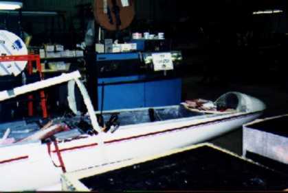
December 1998: As soon as my place of employment (I worked for a company designing/building large power supplies and selling batteries) shut down for Christmas I haul the HP into the plant to start work.
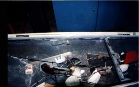
After stripping everything out of the cockpit (including all the bolted down stuff), work started. The project would be attacked in 7 stages: fuselage side rails, nose re-profiling, hinging, turtle-deck front, canopy frame, Plexiglas installation, and then complete the remainder of the turtle-deck.
We used fibreglass for the whole project, using negative moulds as much as possible to create the required parts. This will allow new parts to be fabricated easily if mistakes/accidents/or cracks occur. The project ended up being somewhat larger than expected as we had no experience at all in fibreglass construction techniques.
|
These ended up being quite easy to form. After clikoing a piece of Plexiglas to the inside rail (rising to 1" above the existing rail), a lay up of 6 layers of 6oz glass across the rail and up the plexi. Since these rails have a lot of weight applied to them in the process of getting into and out of the aircraft we figured that this kind of strength would be necessary. When cured, blind fasteners were added to attach the new glass rails to the steel ones using machine screws. Once the inside angles were done, an outer mould was built from plexi and oak When cured, blind fasteners were added to attach the new glass rails to the steel ones using AN3 bolts. Once the inside angles were done, an outer mould was built from plexi and oak. |
 |
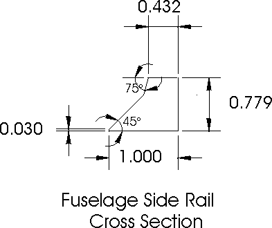 |
After filling the center of the profile with blue foam 6 layers of glass were laid up on top and the outer mould put into place. The end cross section of the side rail ended up as shown in Figure 1. This section was arrived at after computer modeling with the goal of having rails that would seal well (we tie our ship out for the summer) without having interference when opening and closing. |
|
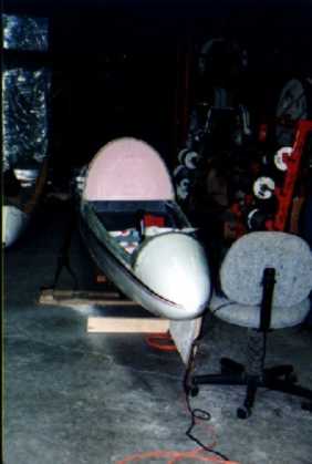
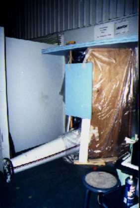
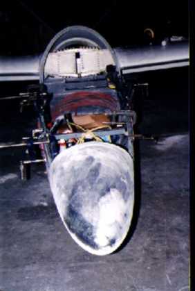
| Since the plexi we blew is not large enough to replace the whole HP14 original canopy, we had to re-profile the nose somewhat to make it fit. This was done using some pink or blue styrofoam, carving and sanding it until we had the shape desired. |
|
|
Then, a little bit of router work added edges so that any water getting in would be guided to the outside of the plane. After a bit of work blending all the edges into the side rails and the nose, and a couple of coats of epoxy to seal the foam I was ready to make a mould off of this plug. This was done right on the plane, so the whole area had to be waxed to make sure that the mould could be removed later.
When laying up the glass, a piece of plywood to force the glass down into the corners was added. This also made sure the mould would be stiff enough that it would not deform when the actual part was formed later. After curing, a little bit of filling and sanding and the mould was ready.
| We were told around this point that for maximum strength in glass structures you want to minimize the amount of epoxy used (while still wetting the cloth out) and compressing the layers of cloth together. In the previous photos you can see that many weights and clamps to compress the structures. It was about this time we became frustrated with using all these weights | 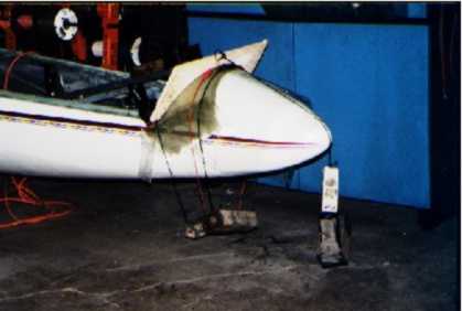 |
 |
|
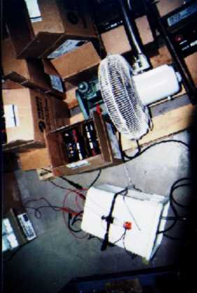
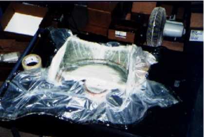
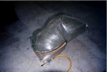
(they are hard to handle, and never stay where you put them), so for the next steps a vacuum bagging system was built. This works better since it applies even pressure everywhere, giving a nice consistent material thickness, and when using peel ply, and an absorbent fabric excess resin is removed. Ours was built out of a little airbrush compressor, a 5-gallon pail with lid, and a switch. The compressor was hooked up from the inlet side to the pail, and then from the pail to the vacuum bag. By putting the switch against the side of the pail it was set up so that the compressor would run until the pail would begin to implode, opening the switch and shutting the compressor down. This would regulate the system to approx. 4-5 inches of vacuum, which seemed to work reasonably well. We tried to increase the vacuum even more, but unsuccessfully as the 5 gallon pail ended up being about 2 inches thick. Later we tried using a piece of 6" ABS pipe, with a vacuum regulator and managed then to get up to ~20 inches of vacuum. The compressor would run a bit hot after a while so a fan was added to keep the temperatures down, since a part would be in the bag for 12 hours or more usually. Boxes were added around the compressor to keep it in one place, as otherwise it would go for a walk around the plant floor it vibrated so much. |
 |
|
The vacuum bagger complete, the new nose profile was laid up, and placed into the bag. This seemed to give much better results, as there were no problems with the glass lifting away in the corners of the mould where considerable problems had been experienced before. After the part had cured in the mould we were at a bit of a loss as how to remove it from the bag without leaving bits of plastic all over the part. Then the answer occurred to us. If vacuum got it in, air pressure could get it out. A couple of PSI of pressure back into the bag succeeded in slowly peeling the bag off the part without any tears in the bag or leaving any plastic attached to the parts that we had moulded. |
 |
 |
 |
 |
|
Now that the part was cured and out of the mould, a few hours were spent trimming the excess cloth off and fixing the few defects (pinholes and a few small voids in corners). Then the part was glued onto the fuselage side rails (with a couple of layers of glass on the inside to reinforce it). To date this part of the structure has proven itself strong enough to move the aircraft by pulling on it without any problem. |
 |
At this point we computer modeled the canopy hinging system, and a fiddled till we had something that seemed to work. We then built up a compete mock up of the fuselage side rails, nose, and wing roots to check the hinging and fit of the proposed canopy (sorry, I forgot to take photos). We quickly made up some hinges (They could never have been trusted in the plane) and checked that everything would clear the leading edge of the wing again.
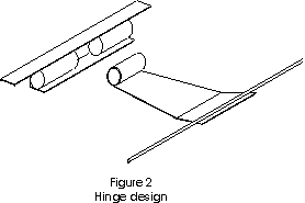 |
The hinge design arrived at is bolted to the bottom of the 1" steel tube rails along the side of the cockpit, with the portion of the hinge attached to the canopy sticking in through a hole in the fuselage skins. Steel ~0.050" thick was used to make the hinge, with ¼" ID tube for the bearings and ¼" OD rod for the axle. The bearing tubes were reamed out by .020" or so afterwards for clearance. Terry Healy, a friend of ours was kind enough to weld up our hinges as I don’t consider myself to be very good at aircraft grade welding (I can do well enough with a MIG welder and 1/8" plate, but no such luck with thin stuff). |
| The bearing tubes had a total length of ~1" for each portion. The hinge line itself is just inside of the fuselage skins, and the hinges protrude out beyond the skin and then up to the canopy frame. Using this route allows the canopy to swing up and away from the fuselage side rails when opening to avoid interference. See Figure 2 for details. The rod welded near the end of the one piece was to create more material for the fibreglass canopy frame to hold on to. The angle portion welded on below the hinge makes sure that when the canopy is removed (in emergency or otherwise) the hinge cannot slide into the fuselage and get hung up. Figure 3 shows a cross section of the fuselage side through the hinge. The hinge itself sticks out from the fuselage side by 0.050" of course, and we used a bit of epoxy and microballons to fair it in. | 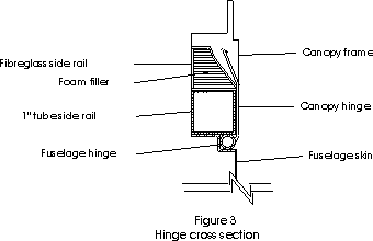 |
Some may wonder about the alignment of the hinges (the axis of the 2 hinges will not be in a straight line due to the curve of the side rail), and by using 1/4" rod that is formed to the fuselage curvature, and .050" steel on the hinge arms allows enough flex to the system that this has not been a problem.
| The turtle deck front edge has to be completed at this point so that the canopy frame can be made next. This edge is determined by the clearances desired between the canopy rear edge and the wing leading edge. The turtle deck itself will be left for last so that it can be profiled to smoothly transition from the canopy to the tail boom. | 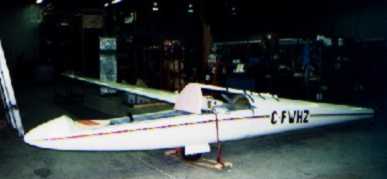 |
 |
 |
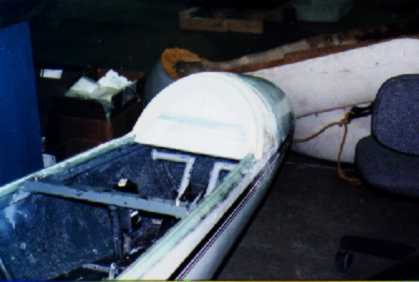
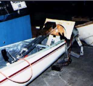
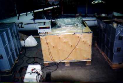
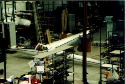
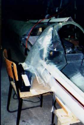
As before, a plug of foam was made, and shaped to what was wanted. During the construction of this the ship had to be partly rigged to make sure that the canopy when installed would not hit the leading edge of the wing (we used a wooden mock up of the canopy frame to check initially). When the plug was in an acceptable position it was tied to the tail boom as shown in the picture to keep it from moving during later stages. Foam mouldings were then made to transition the turtledeck into the previously completed side rails.
| When this was complete, the fuselage was waxed, and then the mould (don’t forget to seal the plug first) laid up right on the plane. Again a piece of plywood was added for stiffness, and make sure that the glass was right into the corners of the plug. The actual part was made in the usual fashion at this point. | 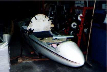 |
 |
|
To prevent the turtle deck from moving around, we then made locator pins out of 1/4" steel rod and added holes to match on the fuselage side rail. About 2 to 3" was cut off of the fuselage side rails and grafted onto the turtle deck to make a place to glue these locator pins into. |
 |
 |
 |
A friend around this time chose to tell us that if you increase the temperature that you are working at you could accelerate the curing of the epoxy considerably. This proved to be a real time saver when bonding pieces together and filling pinholes as we could accomplish more in a day. An electric forced air heater and a plastic "tent" is a lifetime saver. With the rear limits of the canopy frame now defined (and locked into a stable position), we were ready to get onto the hardest part of the job, the canopy frame itself. |
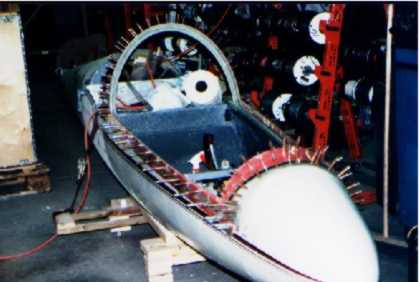
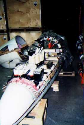
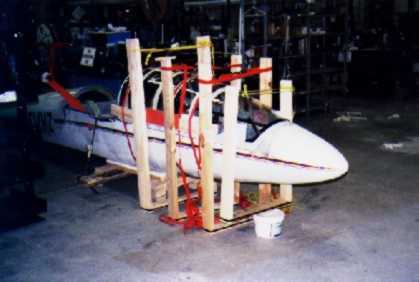
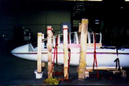
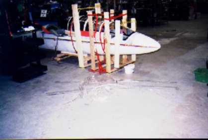
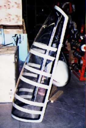
| Since all of the surfaces that the canopy frame comes into contact with have been made, now we could start to make the moulds for the canopy frame itself. All of these were fabricated out of Plexiglas, and clikoed onto the fuselage side rails and the front and rear profiles. By the time all of these were completed, the HP14 looked like some sort of hedgehog! | 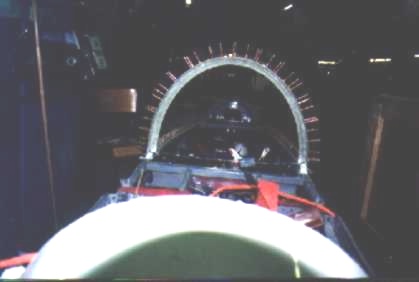 |
 |
Now, with just the inside moulds installed on the plane, and everything waxed, it was time to start the lay up. To begin with we tried to lay the glass up in layers all the way around, and then go onto the next layer. Then, after enough layers we planned to put the outer mould on so that there would be a minimum of voids in the corners. This proved to be a complete disaster. Before three layers of glass were completed all the way around everything just fell off the plane due to its own weight.
| At this point, we decided to put the outside moulds on, and we would stuff the glass in (using the same width of cloth (~2-3"). After a couple trips around using this technique, we flipped the hinges up, and then continued on. After many laps this way, we had the mould filled, and it was time to put the top on. When all this was done we compressed the mould pieces to make sure that there was a minimum of voids in the lay up. | 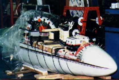 |
 |
 |
It took a few clamps, a couple of pounds of weight, and a bit of banding to compress the moulds to our satisfaction (can you tell I worked for a battery and charger company?). By the time this step was all done we had been working on it for over 14 hours (good thing we used the slow hardener in the epoxy resin, and the plant temperature was a little bit cool that day), and I was in hot water for missing most of my mother’s birthday party. I guess we live and learn, never start a large lay-up job when there is any sort of life threatening deadline to meet the same day.... |
|
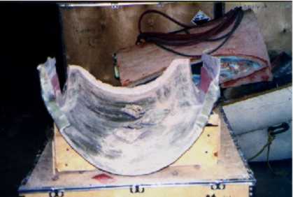
After a couple of days to allow the resin to cure (we used a mix that had an 8-12h+ working time at 20C, and a 72h+ curing time to make sure that we had lots of time, and we needed all of it) the frame was popped out of the moulds to see what we had ended up with. Once out the canopy frame turned out to be structurally strong enough (I could barely bend any part if it, it was stronger way beyond what we expected).
|
 |
 |
|
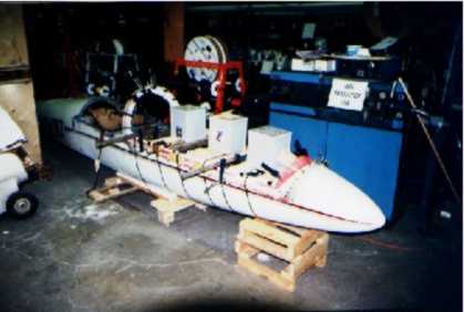
There was a "little bit" of flashing around the edges, and a little bit of time with a die grinder with a cut off wheel made short work of that problem. If you have noticed the different colour of the frame compared to the previous parts fabricated, this is due to our finding out that pigments for epoxy resin exist. We used a white pigment for all parts from the canopy frame on to reduce the amount and effort required in priming/painting to get a nice white colour when everything was done. |
 |
|
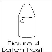
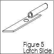
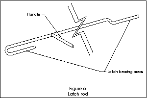
After cleaning up all the edges, and filling any defects in the frame all was ready for the next step: the latch. Latching posts were then fabricated out of ½" steel rod as per Figure 4, latch slides out of .050" and ¼" ID tube like Figure 5, and a latch rod out of ¼" rod like Figure 6. Assembly of the latching system was pretty easy; two holes 0.189" were drilled through the closed canopy frame and through the fuselage steel tube side rails. We then removed the fibreglass side rails and enlarged the holes through them and the |
 |
 |
 |
canopy frame to ½". .With the posts loosely screwed to the side rails, and the slides laid onto the canopy frame I then installed the latch rod. With everything aligned and in place we then bonded the slides to the canopy frame. |
 |
|
Note: After a couple of years use, I have decided to change the latch rod. Depending of temperature the system described works from easily (when cold) to very difficult (when hot) due to the varying expansion of all components with temperature, and the flex that the latch rod demonstrates when any amount of force is applied to it to overcome slight misalignments. This coming winter I plan on replacing the rod with 2 lever driven rods that will be easier to operate. With the latching system complete it was time to start |
 |
 |
|
the cosmetic work… Like all the covers over the edges of the canopy frame. These were made by filling all the edges with foam and then sanding to the desired shape (a nice arc). We then laid up 2 layers of 4 or 6 oz cloth with a black pigment added to the resin on top of the foam. Because a mould was not used we ended up with a nice low gloss textured surface that does not cause much reflection in the canopy. Now that the canopy frame was complete except for the installation of the plexi, we decided that we should try to post cure the resin for maximum strength. This requires heating the parts to >50 degrees C, with the parts either in the moulds, or on the plane installed in their final resting places so that no deformities would be added during the post curing process. As I work for a company designing large power supplies this did not’t seem to be a big problem. My laboratory was almost big enough to roll the fuselage in, and I had plenty of power supplies that I figured could use a good "heat run". We rolled the ’14 into the room, hooked up the power supplies with big heaters as loads (all in the room), closed up the doors as much as possible and went home for the rest of the weekend. My temperature logger recorded the highest temp as being 45-50 degrees C, so we were close. |
 |
|
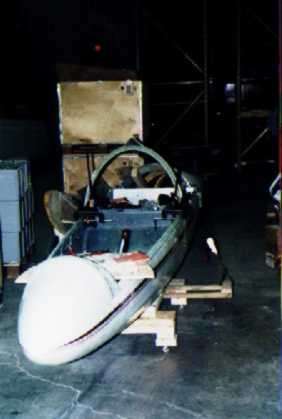
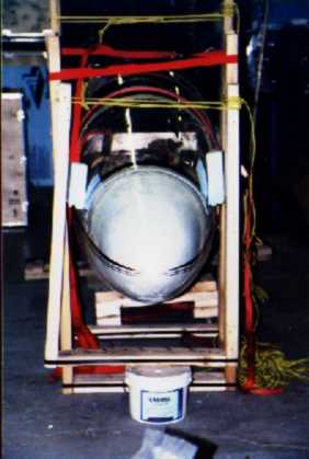
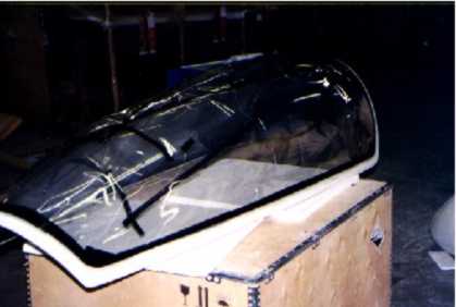
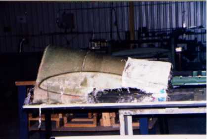
This was the scariest portion of the whole project. Time wise the canopy installation only took 1 day (say 10 or 12 hours, we were very cautious), but it had the potential of being the most expensive mistake in the project. As such we enlisted the help of a fellow club member Jock Proudfoot who has done this a number of times helping other home builders The first step was to determine which portion of the canopy we were going to use. This step would determine the profile of the new canopy. A great amount of time was spent sliding the canopy blank fore and aft trying to find the most pleasing profile |
 |
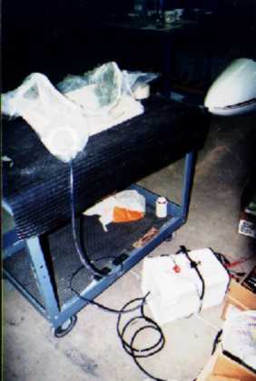
| After this we built a "stand" for the plexi to support it as it was being cut. The stand was nothing more than 2 pieces of pink foam cut to match the canopy profile, attached to a couple of 2X4’s to hold the foam. | 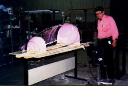 |
 |
|
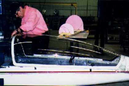
After marking off the canopy with a removable marker the cutting began. We tended to be very conservative, removing 1/8" to 1/4" at a time, and then checking the fit of the canopy on the frame after each cut. A ¼" die grinder with a 3"X1/8" wheel was used to make all cuts. To prevent damage (scuffing/scratching) to the plexi from the "band" clamps we put a layer of masking tape on the canopy before clamping. When we had achieved an acceptable fit it was time to attach the canopy to the frame. We put down a layer of cabosil and epoxy on the frame, and put canopy on top. We used "band" type clamps (otherwise known as ratchet tie downs) to hold the canopy down. We had problems holding the canopy to the side rails, so we made up large "C" clamps out of scrap 2X4’s to hold the plexi in place with foam blocks to prevent damage. Once the canopy was strapped into place, we added brass wood screws to act as a "rip stop" attachment in addition to the glue bond. |
 |
 |
 |
|
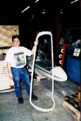
After all of this it was time to clean up and see how much of the plexi we would be throwing away. As can be seen there was a considerable amount of scrap (and the photo doesn't show any saw dust!). |
 |
 |
|
The next day when we came in, removed all the clamps, and removed the canopy from the fuselage. We then masked off the plexi so that when filling the gaps between the plexi/frame joint we would not get epoxy onto the Plexiglas After filling/sanding was complete the masking was replaced and we then painted the frame. |
 |
 |
|
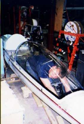
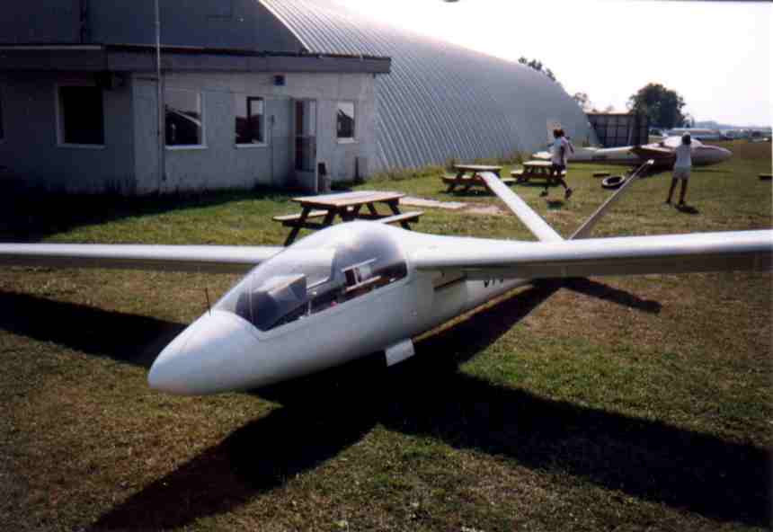
Alex and I made a change to the basic HP14 canopy profile during this process. I am 5’6" tall, and Alex is 6’ + something, so fitting both of us in the cockpit requires some work beyond just changing the rudder pedals. Alex ends up slouching right down, and even then ends up with very little headroom to the canopy, so it was decided that the new profile would give more headroom. We ended up adding about 2 ½" more headroom at the rear of the canopy frame. With the plexi curved in the way that it is, this give I would estimate at least 3" more headroom above the pilot's head and this makes the cockpit much roomier than it used to be. The headroom is so much that I have not hit my head on the canopy since the change (even when flying on the ridge in Pennsylvania). It also might make in flight rudder pedal adjustment possible, with a very flexible pilot. |
 |
| After the canopy was complete we also decided to add a clear vision panel. To do this we first made a plaster cast of the canopy inside profile where we wanted to put the window. We then marked out and cut the opening in the canopy for the panel. By heating the plaster cast in the oven with a piece of ¼" plexi on it we were able to make a panel that fit the canopy perfectly. After cutting the panel ¼" larger than the opening and routing the edges 1/8" deep and 1/8" wide we ended up with an excellent fitting panel. The rails were made out of ½" plexi and had the channels routed into them. With a little bit more drilling and counter-sinking we had a near professional clear vision panel. See the other construction note on Wayne Pauls' HP web site for more details. | 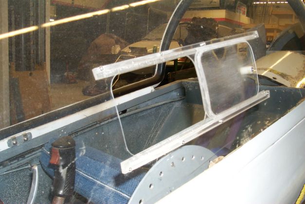 |
We made two mistakes during the plexi installation process. In the first, we were not completely happy with the profile of the canopy, so we pulled the plexi down with the bands to give us the shape we were looking for. While it now looked great, this created stress in the plexi/frame, which once removed from all the clamps showed up. The front and rear bottom corners of the frame were pulled in by this stress, and the middle of the sides were "sprung" outwards. This forced us to later do a lot of rework to the fuselage rails to make the front and rear fit better, and to end up "building up" the fuselage sides so that the canopy blended in better.
In the second mistake, when we were drilling/countersinking for the mounting screws on the canopy we had a small crack start forming from one of the holes. We very gently put the screw in, and hoped for the best. When we came in the next day to remove the clamps the crack had propagated about 3" up the side (thankfully not in the normal field of view). We stop drilled it (which has worked well so far). What should have been done is drilled out the cracked hole, filled it with epoxy, and drilled a new screw hole elsewhere.
|
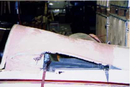
With the canopy complete it was time to start on the last piece of the puzzle. Blue foam was used again to give rough shape to the turtle deck, coated with epoxy for protection. We then got out a can of every bodyworker’s favorite. Bondo. This was to be the most expensive plug built for the project as 27Kg (about 60 lbs) of body filler ended up being used on the turtle deck plug. This part of the project seemed like it would never end. Add some body filler, wait for it to cure, and then sand most of it off. It seemed to take a couple of weeks of building up the plug and fiddling with it until an acceptable shape was achieved. |
 |
| We ended up rigging the ship a couple of times during this process to make sure that the turtle deck fitted to the wings properly, and that the fillet between the two looked acceptable. From what Dick Johnson’s flight reports say this can be a critical area affecting aircraft performance. |
|
 |
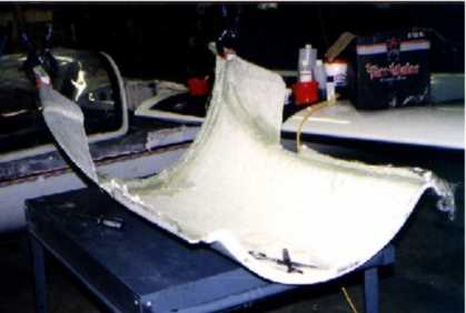
| After much work, it was time to start the mould. We decided to try and use polyester resin on this mould as we were running low on epoxy (and polyester is much cheaper). Many have no problems using polyester resins, but we had lots. The polyester hardens so quickly we did not have much time to lay the glass into the corners. With much perseverance something useable was achieved. After adding a wooden frame for stiffness we popped the plug out. It took some more work to fix it up to a usable state as the polyester resin hardened so quickly that we were unable to get the corners filled properly. Adding some body filler fixed those problems. | 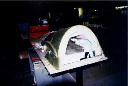 |
|
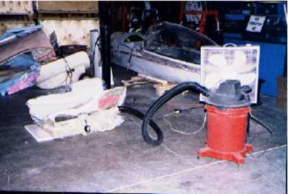
Laying up the actual turtle deck brought to notice a new problem. The wooden frame we added kept puncturing the bag when vacuum bagging (we didn't know about mastic or extending mould edges at this time). We ended up using a shop vacuum to do the job (low pressure, but very high volume) which gave better than |
 |
 |
|
nothing results (it generated about 2-4 inches of vacuum). Once the turtle deck was out of the mould the next task was to attach it to the front edge that was previously built. We again rigged the HP to make sure that everything |
 |
 |
|
was fitted correctly. The two pieces were tack glued initially, and then we took everything apart and laid a couple of layers of glass across the joint on the backside. Now, because the canopy sides had flared out we stripped the hull sides to bare metal, and then built the sides back up to match the canopy profile. From this point the rest of the job was finishing work: filling, sanding, and painting (and lots of all 3). |
 |
 |
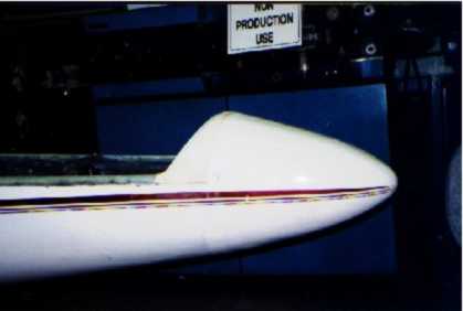
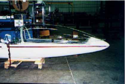
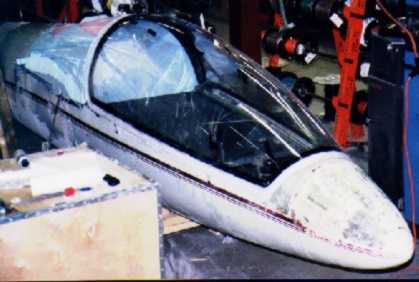
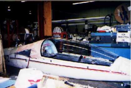
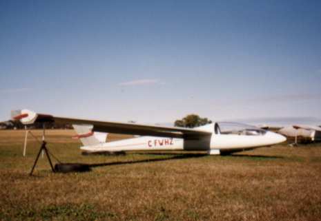
The end result: we were quite happy with except for the two mistakes detailed earlier. The new canopy fixes all the problems we had with the old one. It looks good, does not leak much air (we still need to do some fine sealing work), it has virtually no optical defects, and it has lots of headroom (I hate hitting my head in flight).
Due to the large size of its canopy the HP has been renamed in jest a DG14 by a couple of the members . This size has turned out to be an advantage in my opinion, as I never suffer from having ice cold feet when flying the '14, even in the fall or at high altitudes. Fortunately we have a very effective NACA style inlet under the right wing root to provide ventilation to compensate on the hot days.
As for the costs, they can be looked at in two ways. Materials costs were quite reasonable (We would estimate at less than $1500), but the time investment required is pretty severe. We logged a total of over 450 hours over 4 or 5 months to complete the project.
I would like to thank Terry Healy and Jock Proudfoot for their help during this project. They helped during difficult portions, and were always there when we needed questions answered or needed someone to bounce ideas off. They were remarkably tolerant of the trials and tribulations of first time fibreglass/plexi workers.