HOME-BUILDERS’ HALL
by Stan Hall
HOW TO DESIGN AND BUILD YOUR OWN
HYDRAULIC FLAP SYSTEM
Part 2 of 2 Parts
SOARING November 1978
Page 34-38
To the Shop
In Part I of this article you and Homebuilders’ Hall "designed" the hydraulic flap system on Sheer Klieg’s HP-14. We did this by filling out a table which, by way of a little straightforward arithmetic, developed the basic system parameters. The idea behind the table was, of course, to give a step-by-step procedure which you can use in working out the parameters for your own system. Now that you understand the process and have, in fact, developed your parameters (you have, haven't you?) we trust you are now prepared for the next step - the actual building and assembling of the hardware. Let's follow Figures 3 and 4 and make chips.
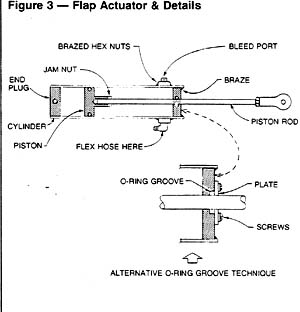
Building the Flap Actuator Cylinder
To simplify the discussion a little, we'll assume that the cylinder includes the two end closures (plugs). The cylinder can be made of any kind of seamless steel tubing you can find. The accent is on the seamless, because the inside will later be honed to an ultra-smooth finish. (Sheer Klein tells of the plight of Don Fisher, an HP-14 builder in California. Don inadvertently purchased welded tubing, which has a seam on the inside. He eventually got that seam cleaned out, but he says he isn't talking about it until he stops aching.)
It is important that the inside diameter of the tubing stock used for the cylinder be as close as possible to the nominal outside diameter of the O-ring seal. This is because machining (boring) the inside of a thin tube to accurate dimensions can be a trying task, even for a machinist. Better to leave the I.D. as it comes.
Table 4
|
AN6227B O-ring Groove Dimensions |
|||
|
O-ring Dash No |
Groove dia. in piston, in. |
Groove dia. in plug, in. |
Groove width, in. |
|
1 thru 7 |
Cylinder I.D. minus 0.113 |
Rod diameter plus 0. 113 |
0.094 |
|
8 thru 14 |
Cylinder I.D. minus 0.179 |
Rod diameter plus 0.179 |
0.140 |
|
15 thru 26 |
Cylinder I.D. minus 0.245 |
Rod diameter plus 0.245 |
0.188 |
|
27 thru 46 |
Cylinder I.D. minus 0.374 |
Rod diameter plus 0.374 |
0.281 |
Within the range of diameters of interest, the AISI 4130 (SAE 4130) tubing catalogs show I.D.'s which are either .009 inch larger or .005 inch smaller than the nominal O-ring diameter. Since O-ring groove diameter (Table 4) is based on cylinder I.D. or piston rod diameter, either side of nominal tube 0. D. within the limits stated should be acceptable.
The length of the cylinder should be at least a couple of inches longer than the actuator stroke, not only because you'll need some added length for the end closures, but because you won't be able to hone uniformly, right down against one of the end plugs. This is because the plug is brazed in place, and you need a smooth surface for the piston O-ring to ride on along its entire stroke.
Near the flap-end of the cylinder, drill a hole through the cylinder diameter (clear through - both walls, two holes) and secure a large hex nut over each hole by means of a long, temporary through-bolt. The nut thread size is unimportant at this stage so long as it is smaller than the tap drill for a 1/8 pipe thread and so long as you can pass a bolt through the two nuts to hold them in place during brazing - which is what you do next.
Braze the nuts in place, being sure that you fill in all around with plenty of rod. Next, take out the temporary through-bolt and drill and tap both nuts for a 1/8 pipe thread.
As installed in the aircraft, the lower of these nuts takes the fitting for the hydraulic line from the pump. The upper one is an air-bleed opening in which you will install a removable 1/8 pipe plug. (Instead of tapping 1/8 pipe here, Sherb tapped 10-32 to take a standard automotive bleed hose. He used a headed plug and, to assure sealing, a lead washer under the head.)
The brazed-in end plug comes next. The plug O.D. should be such that you'll have to tap it into place in the cylinder I. D. Not a press fit. Snug.
There are at least two ways to cut that tiny O-ring groove in the plug. Both require the use of a lathe. One method calls for grinding a special bit. If an expert machinist does the grinding, okay, but it's a tricky job nevertheless.
A simpler technique, shown in Figure 3, is to cut the groove O. D. right into the face of the plug, to the depth of the O-ring cross section diameter, plus a little, and screw a plate over it. You won't need a specially-ground lathe bit for this operation.
The plug on the opposite end of the cylinder has no O-ring, of course, and it's much simpler to make. Its O.D. need not be precise, just so it slips freely into one end of the cylinder. Drill a small air-bleed somewhere through the plug.
The plug is secured to the cylinder by a through-bolt which also secures the actuator to the sailplane structure.
|
|
The next step is to braze the plug with the O-ring groove into one end of the cylinder. To assure proper alignment of this plug (we don't want the piston rod to bind), pass a rod through the plug and into the closure on the other end. Be sure the O-ring is not installed (or you'll fry it) and braze the plug in place. Try to get all the way around with the brazing in one pass to minimize heating, otherwise you may get scaling on the inside - which you'll never get out. If you can silver-braze, all the better. Silver brazing is cooler (and usually stronger) than brass brazing.
Honing the Inside of the Cylinder
After all brazing is done, hone the inside of the cylinder with an automotive brake cylinder hone. You can purchase this tool from your local auto parts store. Get the kind with stone grinding elements, not the cheapie kind that uses emery cloth. These latter are only good for removing light rust and corrosion. They do not hone. The hone is designed for use with a drill motor, which should be operated at something less than full throttle. I wouldn't recommend a pneumatic drill motor. Much too fast.
Use a lubricant while honing. Honing Oil (machine shop) is best, but kerosene will do. Don't use motor oil; it puts a glaze on the surface. Wear dirty clothes, and don't rush the job. With care, you can probably do the job with one set of cutting stones. If not, they're replaceable.
Making the Piston
You can make the piston out of any metal you can find around the shop, but aluminum alloy (any kind) is preferred because of its good machinability.
Turn the O.D. of the piston down in the lathe until it slides smoothly inside the cylinder with, say, not more than .005 to .010-inch clearance on the diameter. You'll have the same problem making the O-ring groove as with the groove in the end plug - and you can make the groove the same way. Later on we'll be discussing O-rings and the groove dimensions they require.
Making the Piston Rod
As Figure 3 shows, the piston rod is simply a rod threaded at both ends. One end screws into the piston (don't forget the jam nut) and the other into the rod end fitting that picks up the flap drive horn (jam nut here, too).
The only thing critical about this rod is that it be smooth. Otherwise it will chew up the O-ring in the end plug and permit leakage. In the aerospace industry, such rods are normally chrome plated, but at the pressures we're talking about for sailplanes, you can get a sufficiently smooth finish by using drill rod.
Assembling the Actuator
The actuator assembly procedure is straightforward. Do it with clean parts, in a clean place, and with clean hands. Wet everything with hydraulic oil first.
With the removable end plug removed, insert the piston rod through the brazed-in plug. Be careful you don't abrade the O-ring (installed in the plug beforehand) with the threads on the rod. The best way to prevent this is to wrap the thread with a layer of very thin plastic (like Saran Wrap) and slide it carefully past the 0-ling. Don't use masking tape. Too thick and wrinkly. The best way to minimize O-ring damage is to undercut the thread so that it is smaller in diameter than the rod, if the operating loads and attendant stresses permit.
Next, screw on the piston (O-ring installed) and tighten down on the jam nut. If the actuator end-plugs serve also as flap-position stops (a good approach), you can at this point slip a short oversize tube over the piston rod. This tube, cut to the proper length, will come up against the brazed-in plug and the piston at the flaps-up position. The flaps-down position is established by the piston coming against the plug at the other end.
Sliding the remaining end-plug in place and securing it temporarily with a bolt completes the assembly, except for the rod end which you'll get to later. Wrap the actuator in a clean cloth and put it away while you build the rest of the system.
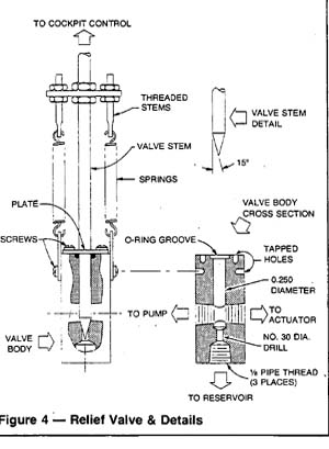
Making the Relief Valve
The relief valve comprises a body and spring-loaded valve stem with O-ring. That's all.
Make the body from square or rectangular aluminum alloy bar, any kind. If you don't have aluminum, steel or brass will work just as well. The size can be anything you can find around the shop, with a minimum of perhaps an inch square. The length of the body should be the length of a No. 30 drill, minus whatever drill length is required for chucking (you'll be drilling No. 30 full-length, later).
Drill all the way through the diameter of the bar near one end and thread each end of the hole with a 1/8 pipe tap, taper-reaming beforehand if possible. As shown in the schematic of Figure 1 (in Part 1 of this article), one end of this through-hole picks up the hydraulic line leading to the flap actuator. The other end goes to the pump.
|
|
The schematic shows the relief valve standing out there all by itself, supported by the hydraulic lines. It is shown that way to make the schematic easier to follow. Actually, the valve can (should) be mounted directly on the pump. So, rather than providing a line leading from the valve to the pump as shown, simply screw a 1/8 pipe-threaded nipple into one or the other tapped holes in the valve body and screw the whole affair directly into the pump "out " port.
The next step gets a little -tricky because you have to drill a couple of very concentric holes down through the length of the body for the valve stem, which seats against the smaller of them. Consider the two holes you drilled and tapped in the step above to be at the bottom of the valve body.
From the top end, drill down the long axis until it intersects the tapped through-hole, then carefully drill on down farther, past the tapped holes for another .06 inch or so. If you don't drill on past a little, your valve will leak. Use a brand-new 0.25-inch diameter drill.
It is really best to do this in a lathe because you have to drill the rest of the way with a (brand-new, again) No. 30 drill, and the holes need be concentric. Using new drills helps assure this. Even so, unless the smaller drill centers itself exactly in the bottom of the larger hole, there will be lack of concentricity.
You can improve this situation somewhat (at the time you insert the valve stem) by lightly lapping the stem into the smaller hole with fine valve grinding compound. One light tap on the stem with a hammer will also help, states Sherb.
The reason for requiring concentricity is obvious; if the holes are not concentric, the tapered end of the valve stem will ride along one side of the No. 30 hole - and the valve will leak. You'll wonder why you're running out of runway so quickly. Surprise! Surprise! (Good test: suck on the valve. If you can’t get your tongue back you have a good valve!)
With the valve body still in the lathe, counter-bore the 0.25-inch diameter hole for the valve stem 0-rinc, seal. Complete this end of the valve body by drilling and tapping four holes, two adjacent to the valve stem (for the O-ring retainer) and two in the sides to hold the clips for the springs which hold the valve stem down into the No. 30 hole. This No. 30 hole, by the way, vents the hydraulic oil back to the reservoir when the valve stem lifts off it.
Turn the valve body around and drill and tap the No. 30 hole for a 1/8 pipe thread.
The Valve Stem and Springs
Now for the valve stem itself. Sherb Klein made his from a piece of 0. 25-inch diameter brazing rod. If you have trouble obtaining this large size rod in brass, steel will work, too.
As shown in Figure 4, the bottom of the stem is tapered 15 degree. Because the No. 30 hole seals on this taper, the machining must be done on a lathe to give the smooth straight surface required.
The top of the valve stem is threaded so that a metal fitting can be installed to pick up threaded stems to which the valve springs are attached. The stems are threaded to permit spring adjustment without throwing the mechanism which opens the valve from the cockpit out of alignment.
With the fabrication and installation of a plate to retain the O-ring, the relief valve is now complete except for the springs.
Sherb's springs are about 1. 75 inches long . center to center, have an O.D. of 0.25 inch, and a wire diameter of 0.032 inch.
You can compute the approximate spring tension you need at the desired flap-relieving airspeed by determining the force acting on the valve stem from hydraulic pressure and subtracting O-ring breakout friction.
First, determine the pressure on the system by dividing the actuator load (Step 7 in Table 1) by the effective piston area (Step 12). If you're looking for accuracy here, you should add in the effect of the flap-return springs, if used. However, compared with the pressure due to air load on the flaps, the added pressure due to the flap-return springs is not likely to be large and can be ignored.
Second, determine the effective area of the valve stem against which the pressure works. This is simply the area of the 0.25-inch diameter hole minus the area of the No. 30 hole. I get 0.036 square inches.
The opening force on the valve stem will, then, be the pressure times the area. If you'll set the springs for a little less than that (to account for O-ring drag), you'll be in the ballpark. For fine-tuning, of course, you'll need do some flight testing.
You'll find additional information relating to O-ring friction later in this column.
Making the Relief Valve Control
Cockpit control of the relief valve can be achieved by any number of means, limited only by the designer's creativity. Any technique permitting the pilot to raise the relief valve off its seat is likely to work. However, Sherb recommends against using Schreder's method. Dick's system calls for the relief valve to open when the flap handle is pulled completely aft. Sherb reports several close calls, using this technique. Better to have a separate control, he advises. Agreed.
Sherb located his relief-valve control immediately adjacent to the handle, and can bleed the -flaps up a few degrees at a time by blipping the control with his "educated thumb" or can bring them fully up by merely holding the control down.
Making the Reservoir
Any kind of tin can with a screw-on cap will make a good reservoir. The can should be large enough so that when the flaps are down it is still a third full, and when the flaps are up, not more than two-thirds full (to minimize spillage in rough air). Sherb's purchase of a can of automotive brake fluid for some of his aborted earlier experiments wasn't a total loss after all, because he used the can for his reservoir. To keep the fluid clean, he epoxied an automotive fuel line filter to the cap. This filter also provides necessary venting of the reservoir.
The first cap on Sherb's reservoir was the non-spillable kind (used on aircraft batteries). However, the hydraulic fluid eventually disintegrated the ball-check and the debris fell into the reservoir. He now uses the cap that came with the can in the first place, without a ball-check. Thus far. no spillage.
Flap Position Indicator
Knowing flap position at all times is, of course, essential. This requires a cockpit indicator of some sort. As shown in the schematic of Figure 1, Schreder measures actuator stroke and displays it in terms of flap position.
The mechanism between the piston rod and the cockpit will, as in the case of the relief-valve control, provide limitless opportunities for creativity. The actuator in Sberb's HP- 14 drives a little tab in the cockpit by means of an automotive push-pull control, the kind used in the old days to operate chokes. Controls of this type are widely available.
O-rings and Grooves
The AN62271B O-ring is standard in the aircraft industry and can be procured from most aircraft parts supply houses. Table 3 (in Part 1), which shows a range of standard O-ring sizes, was supplied through the courtesy of Aircraft Spruce and Specialty, Box 424 Fullerton, California 92632. (By the way, order their excellent catalog. It costs $2.00, which is refundable with a purchase of $25.00.)
O-rings can be obtained from other sources, too (hardware store, auto parts supply house, etc.) but the rings don't carry the "AN" identification. They appear to come in the same sizes as the AN rings and are probably made of the same material. When I soaked a couple in gasoline and automotive brake fluid they didn't swell or distort, so they may work equally as well as the AN rings.
It is important that the groove in which the O-ring seats provides the proper amount of "squeeze" against the sealing surface. Too much squeeze raises the breakout friction (important in applications such as the relief valve) and too little raises the possibility of leakage.
Table 4 shows the groove dimensions which I recommend you use with the AN6227B O-ring.
For the potential benefit of those of my professional colleagues who may be employed in the "oil business" (hydraulics), and since I hate answering mail, permit me to slip in a little disclaimer right here about this table. It doesn't conform exactly with aircraft standards because, whereas O-rings come in standard outside diameters, steel tubing rarely comes in corresponding inside diameters. Aircraft hydraulic cylinders ar-e almost universally thick-walled, and well-equipped manufacturers can machine bores to provide exactly the right O-ring squeeze.
But in this article we are using thin-walled, off-the-shelf steel tubing for the cylinder. We are stuck with the I. D. and the task is to dimension an O-ring groove that will provide a squeeze that is at least close to the aircraft standard. O-rings tend to be forgiving. This is why you'll note some differences between Table 4 and the table(s) shown in your company's hydraulics design manual.
O-ring Breakout Friction
Since we're discussing O-rings, let's touch briefly upon O-ring "breakout friction." Breakout friction is that amount of force, usually expressed in pounds per square inch pressure, required to move the O-ring itself from a position of rest. It is sometimes referred to as "static friction."
Test data show that below about 200 psi system pressure, the pressure required to break the O-ring "loose" is in the neighborhood of 10 percent of the system pressure, with a minimum of about 3 psi. The friction pressure falls off above 200 psi and eventually levels off at about 15 psi from 1800 psi system pressure, up.
You can use this information in setting those relief-valve springs prior to flight testing.
Making Up the Plumbing
Except for the flexible line which attaches to the flap cylinder, Sherb made all his hydraulic lines from automotive hydraulic brake steel tubing. At the low pressures involved, the use of copper tubing would be okay, too.
According to the Barlow equation, a standard 0.25-inch O.D. x 0.030-inch wall copper tube has a burst pressure a little under 8000 psi. It is standard engineering practice to set the maximum allowable operating pressure at one-fourth the bursting pressure, which in this case turns out to be about 2000 psi. At 100 knots the pressure in Sherb Klein's system calculates to about 440 psi. Lots of safety margin left in this size copper tube.
Whatever tubing material is used, the fittings should be of the flared-tube type, not the compression type. The latter type joint is normally quite good but doesn't have the reliability of the mechnical connection represented by the flared connection.
As to the line to the actuator cylinder, which needs be flexible because the flap cylinder moves, Sherb had an Aeroquip aircraft-type hose assembly especially made up for him. I note that Aircraft Spruce and Specialty offers this service. I'm sure other suppliers do, too. Don't use automotive flex hose-MIL Spec. oil will attack it (see below).
Since custom-made flex hoses tend to be expensive. if you're strapped for cash, you can give copper tubing a fair amount of flexibility by making a large loop in it right at the flap cylinder, with the diameter centering on the cylinder attach bolt. The loop should be in the plane of the flap-drive hom so that as the flap moves up and down the loop diameter changes. It is worth noting that copper tubing tends to become brittle after a considerable amount of repetitive bending, so if you use copper tubing instead of flexible tubing at the flap cylinder, you'd best replace it every I 00 hours or so just to be on the safe side.
You might also consider some of the new high-pressure plastic tubing that is coming on the market. Although I don't have a source for the material readily at hand, I am much impressed by it.
Hydraulic Oil
Sherb Klein recommends the use of aircraft hydraulic oil (the red stuff). Any aircraft parts house can provide it. Ask for Spec. MIL-0-5606B(l) hydraulic oil.
Sherb advises against the use of automotive brake fluid. Apparently it absorbs water, and steel parts tend to corrode as a result. It corrodes in automobile systems, too. If you doubt this, take the cap off your brake fluid reservoir and look.