Cheap Lasers Aid in Alignment of Sailplane Wings
During Assembly for Flight
By
Hugh
Helmick
Introduction:
Installing and removing
glider wings many times over the years, I have sometimes remarked to myself how
very easily assembly and disassembly can be on those rare occasions where
things are really aligned perfectly.
(It never happens when it's extremely hot, or when someone is watching.) I had always assumed that perfect support
and alignment was the cause of this - on those occasions, the pins simply slide
in or out with no pressure at all. I
had read how useful laser beams can be for measurement and alignment
tasks. I asked myself: Why couldn't lasers help in alignment of
glider wings? In recent years,
inexpensive red diode lasers have become available. Conveniently, they are compact, and are widely available as
pointers for office presentations. I
looked at some red lasers, and figured that they would not cast an alignment
spot that would be visible in daylight.
I understood that green laser pointers which would be much more visible
to the human eye, and are becoming available, though still at very high
cost. Finally, an idea struck me while
using the one-man assembly system described elsewhere in this HP Sailplanes
Homepage: It shouldn't be necessary to
see a projected laser spot in direct daylight, and in fact, with the one-man
assembly dolly position controls located under the wings, and with laser
targets under the wings in shadow, the idea would still be workable. The below pictures and captions show what
has turned out to be an extremely repeatable alignment method which allows
glider assembly every time, with the very least adjustment troubles that one
can imagine. Further developments seem possible,
including sailplanes manufactured with factory supplied lasers integral to the
airframe, even using small windows in the fuselage sides.
Limitations to the Present Design:
DISCLAIMER / WARNING: Laser light directly impinging on the eye is potentially
damaging to the eye, and must be avoided, even with the low power (<5
Milliwatt) lasers used here. I do not
know of any hazard to the eye caused by these low power red lasers while
REFLECTED FROM A DIFFUSE SURFACE, NOT INCLUDING A MIRRORED SURFACE. EVEN A SMALL MIRROR-LIKE SURFACE MIGHT
POSSIBLY CREATE HARMFUL EFFECT SIMILAR TO LOOKING DIRECTLY AT A LASER, AND BOTH
SHOULD BE AVOIDED. ONE MUST PRECLUDE
CHILDREN OR UN-SUSPECTING ADULTS FROM HAVING EYES DIRECTLY EXPOSED.
The pictured installation on
my HP-18 is not ideal - I did not want to pierce the fuselage for exit of the
laser beams in order to allow the beams to project parallel to the wing
spars. I installed lasers on the
fuselage just forward of the front drag spar, angled aft slightly, under the
wing leading edge. As a result, this
installation has some parallax, but the angles and lengths involved are such
that this is not a noticeable effect.
The beams produce spots on the alignment targets under the wings and
have been quite visible in every situation to date. The laser target and red dot are convenient to the position
adjustments on my wing support dolly.
Location of the lasers at the front of the forward drag-spar has been
very satisfactory, and coincides nicely with the removal of the turtle-deck
during wings installation and removal.
Initially I considered the installation to be temporary, using epoxy to
attach the lasers to bent-up brackets after they are attached by existing
bolts. Initial alignment of the lasers
was accomplished by bonding them in place while supported with small wood
wedges so that their beams strike near the center of a target fastened rigidly
to the wing cuff. (The cuffs are
accurately placed on the wings by aligning them with ink marks on the
wings.) Later, finding that the .065
steel brackets were very slightly flexible, I bonded them with some
low-strength epoxy (5-minute variety) in order to add some more stability to
their mounting. Cross marks added to
the targets with a marker pen. Results
during daily assembly / disassembly have been extremely satisfying: No more ambiguity which way that wing needs
to be moved, less running back and forth to adjust, and pins just slide in
usually.
Conclusion:
This idea really seems to
reduce effort and wear and tear to close fitting glider parts.
This particular installation
is not well adapted to assembly using manually held wing-tips. A person at the wing tip cannot see the red
dot underneath the wing and potentially eye hazard might result, anyway. In the setup shown, notice that one looks
AWAY from the laser source.
Obviously, consistency in
the location of targets and support of the wings and fuselage is central to
success of this or any similar installation.
It turns out that during assembly, the fuselage needs to be rigidly held
in roll axis for consistently easy assembly
(the main gear is retracted with the fuselage dolly elevated to max
height).
During disassembly, it's
desirable to allow the fuselage to freely roll SLIGHTLY as both wings are
lifted upward. This prevents any
preloading of the fuselage relative to either wing, and allows for some wing
flexure while wing support forces are increased. My fuselage dolly is designed to still provide very slight roll
freedom in the fuselage when in the dolly is in lowered position with the main
gear extended. This fuselage dolly can
later lift the main tire just clear of the ground for wheel retract before
going inside the trailer.
I note that the system has
not been demonstrated on an all-composite glider, most of which have wings more
flexible than the HP-18 here. Still, I
should think the technique would be of value on any glider, especially those
that are really difficult to assemble due to large size and weight. Let me know if you try this and have any
ideas for further improvements.......... n413h@iwvisp.com
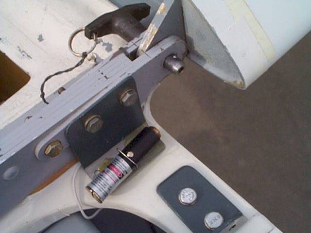
Laser pointer mounted to the forward left drag-spar fitting on fuselage. The small piano-wire clips rotate over the laser switch buttons, to hold the switches "on", as needed. I slotted the end caps for easy replacement of batteries in this tight location. A magnet is handy here for removing depleted batteries. Power from the glider battery might be a desirable option.
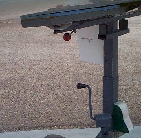
In this case, the one target is attached to the wing support dolly, since it is very consistently located with the wing cuffs when supporting the wings. It is made of a moderately stiff white plastic sheet obtained as notebook dividers, available at stationery stores. This material will not do any damage when touching the fuselage, etc, when removing and returning to the trailer. The "x" marks are added to the corresponding sides of the target sheet when wings are supported as a first step to remove wings from the ship. (In initial setup, first support the wings such that all wing pins are in a sliding fit situation. This needs to be done in the same manner that normally will be used in supporting wings for installation and removal.)
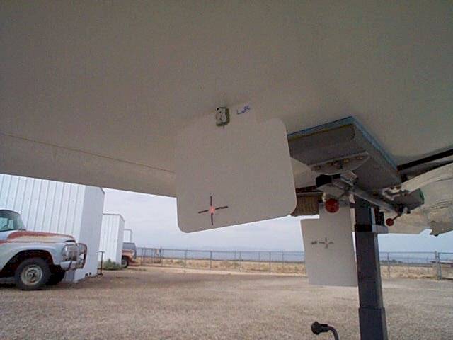
In a later experiment I
tried targets which could be plugged into tiedown attachment holes, as shown
here.