INSTALLING the UDO AIRFOIL
on
RS-15 N5724
by
Doug HoffmanFirst read Udo Rumpf's article on this website: Wing Modification and Re-profiling. There is excellent information there.
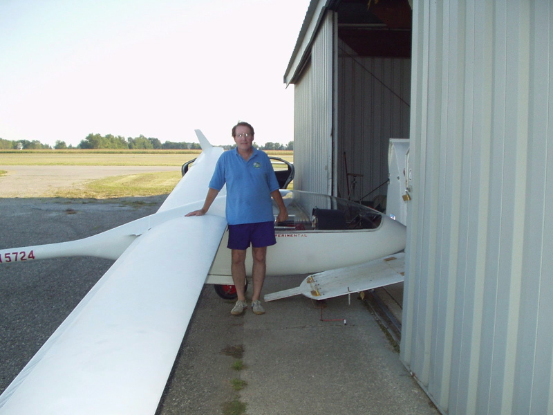
In the fall of 2002 I had decided to install Udo Rumpf's "Super" airfoil on the wings of my RS-15. I believed that I could complete the project over the winter and have the glider ready by May of 2003. Well, while I still believe this could have been done, work and other factors led to me not completing the project until July of 2005. I believe that a more efficient person with the ability to dedicate more time could indeed complete this project over a winter. A better plan for me would have been to have a second glider on hand for flying during the project. Photo 1. is a "before" picture of the glider and pilot. The stock flap top surface metal "extended skin" seals were still in place.
A couple of decisions must be made up front. First, one must fabricate the templates. I chose to use 3/4" birch plywood from Home Depot. The material is easy to work with and not expensive. Others have used aluminum templates cut by highly accurate CNC machining. This would be a nice way to go. But I found the wood templates to be quite adequate, especially since the final surfaces of the airfoil are "hand-sanded" in.
The second decision is what filler material to use. Another person who had installed Udo's airfoil (David Rhyti) recommended using Poly Fiber's Super Fil, claiming that it was easier to mix than thin epoxy with micro-balloons (2 things to mix instead of three, a simple 2:1 by weight mix). Poly-Fiber advertises that Super Fil weighs 3.68 pounds per gallon and Udo indicated that his epoxy/micro mix was about 3.4 lbs/gal. Also, my understanding was that post-cure shrinkage was not an issue with Super Fil (which was true), so I went with that. I found the Super Fil to be very easy to mix, apply, and sand. However, the weight claim may be wrong. The final added weight to my wings was 91 pounds. A bit more than I expected (but it flies great, so I'm not complaining!). In hindsight, if I were to do another wing I would either lighten the Super Fil with micro-balloons or use the same mix as Udo did. I believe the epoxy/micro route would be noticeably cheaper as well. I re-contoured both top and bottom surfaces.
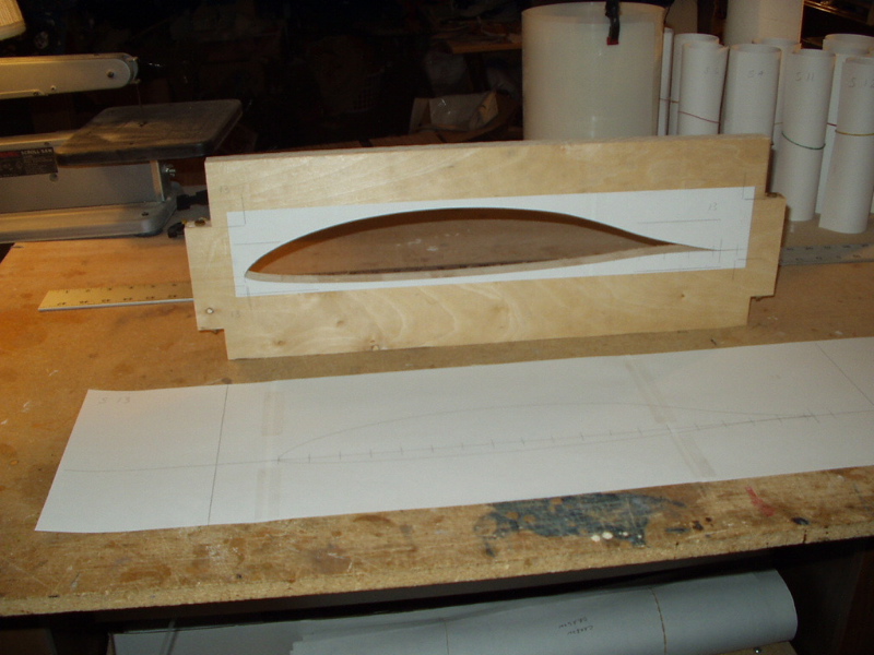
I used a computer program to plot the airfoils on 8.5"x14" paper. The program I used provided alignment and registration marks so it was easy to tape multiple sheets of paper together while maintaining good accuracy. I then used 3M 77 spray on the wood and laid on the paper plots. A bandsaw was used to rough cut the wood and careful sanding was then used to achieve accurate final template shape. By always being careful to keep the template surfaces at exactly 90 degrees to the wood surface I could use the same templates for the right and left wings, with the inboard edge of the templates defining the control contour. See photo 2. I used a total of 14 templates spaced equally at about 21.5" apart.
The metal skin flap gap seal should be removed at this point. Trim it back leaving adequate edge clearance from the rivets.
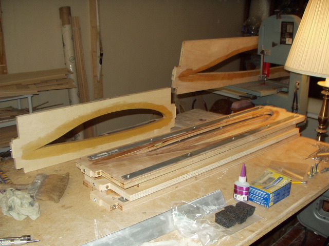
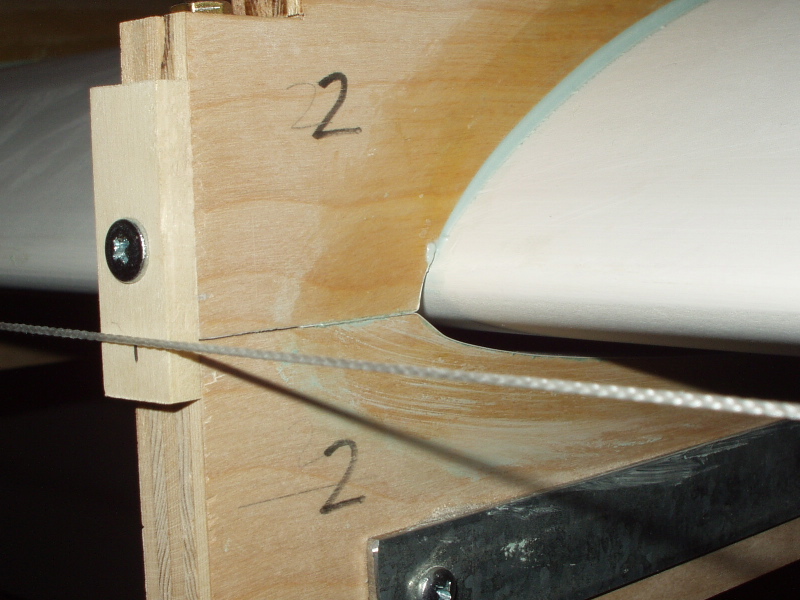
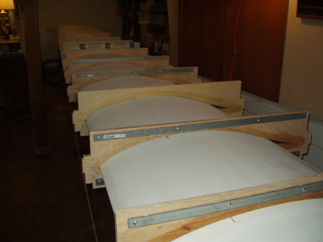
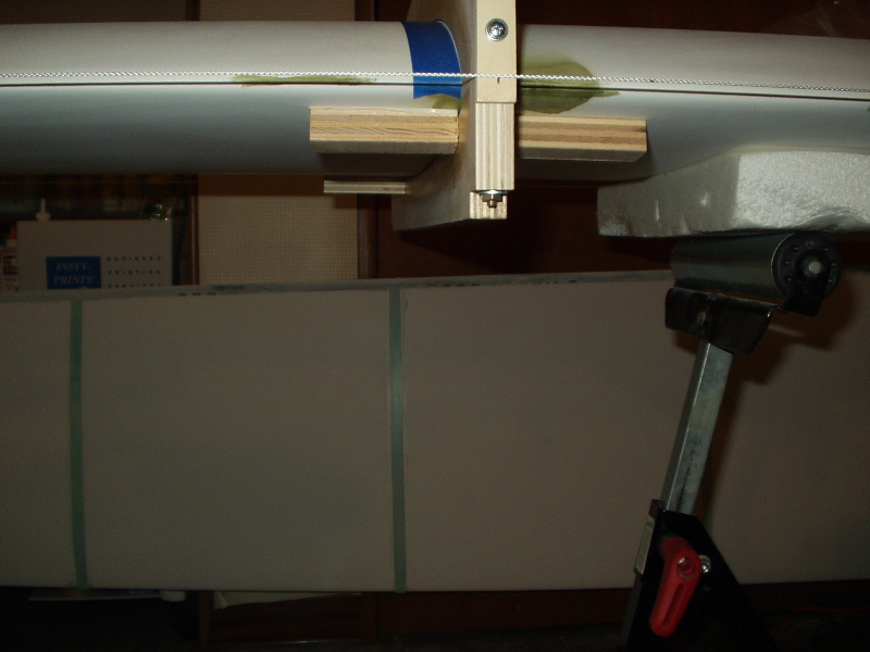
I found that on some of the templates I did not leave enough wood for proper stiffness so I added metal strips. See photo 3. Also note the varnish to seal the wood and the small wood "tabs" added front and rear to allow for accurate alignment of the templates on the wing. See photo 4. where a mason line string is pulled taught for reference. There is a carefully placed pencil mark for alignment on the tab that is covered here by the string.
Careful alignment of the templates on the wing is critical and I believe one should take as much time here as necessary. No doubt there are many ways of achieving alignment. Here are a few techniques that I used. One issue is assuring that the wing is perfectly level when placed flat in the horizontal position. I achieved this by starting with each wing rotated in the nose down position and "relaxed" such that it was in its naturally straight state. Flaps and ailerons were removed at this point. Then, using bits of balsa temporarily glued into the trailing edge channel, I tightly stretched a mason's string through the channel. Marks were made on the balsa at the string intersection points such that this same position, i.e. no bending of the wing, could be reproduced by re-aligning the marks to a taught string when the wing was laid flat on the sawhorses. See photo 5. Also note the use of a bubble level on top of the templates as a double-check of the accurate alignment of the templates. The templates were positioned square to the spar stub surfaces, which are conveniently flat on top. Assuring trueness to the spar stubs assured that each wing half would also be true to the other half, although it might be a good idea to verify this first with the wings assembled on the glider.
Also in photo 5. one can see bits of balsa shoved between the templates and the wing surface. These were sometimes required in order to align the templates. The balsa bits can be left in place when forming the epoxy splines and thus become part of the wing.
I found the Super Fil to be extremely sticky stuff, which of course is good. Problem was, at first I had a very hard time removing the waxed template from the formed epoxy spline without ripping the spline and paint from the wing when the epoxy adhered to the template. Udo suggested using 3/4" plastic tape, which helped a lot. I found that I also needed to use mold release wax (applied to the tape) and "#10" water-soluble release agent on top of that. Then the templates were easily separated from the cured splines. Also, when forming the epoxy splines it helped greatly to apply painter's blue tape to the wing to define the position of the template and help remove excess epoxy (another idea from Udo). The tape should be removed before the epoxy fully cures. Scraping excess epoxy from the sides of the template with a single-edged razor, prior to cure, helped as well. See photo 6. The blocks of wood on the bottom in photo 6. were temporarily stuck to the wing with strong double-sided sticky tape and helped to define the precise position of the template when laying in the epoxy.
After the splines were formed, a black indelible marker was used on the inboard edges to create the control surface hard points. A screed for laying in the epoxy was made from a straight piece of 1"x2" hardwood with mylar glued to the screed surface. I found that the Super Fil could be difficult to get to flow unless a heat gun was used to keep it warm. Too much heat would cause bubbles to form which ultimately became pinholes that had to be filled. But judicious use of the heat gun was invaluable. Also, keeping the Super Fil cans covered by a cardboard box with a (drop cord) light bulb for heat made mixing and screeding the stuff (it is very thick in consistency) much easier.
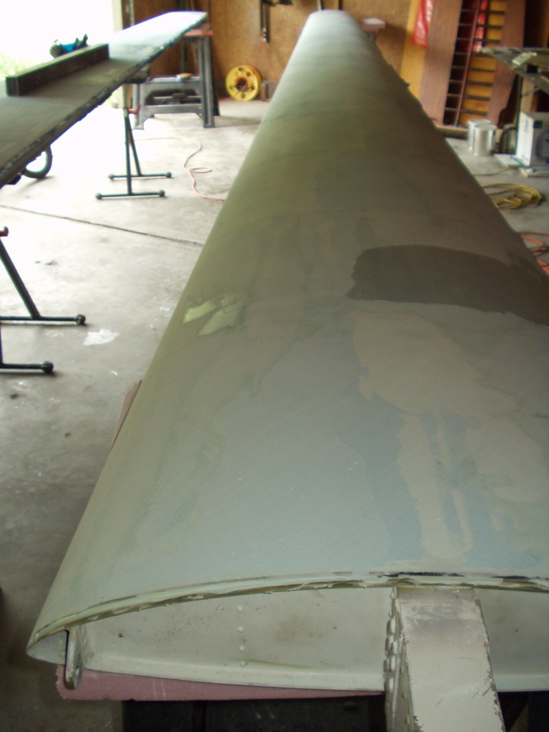
Photo 7. shows the final stages of contouring and sanding the filler. The different shades of blue were due to the variability in color of the Super Fil from different cans. I used a 4' long 2" x 3" rectangular piece of aluminum for sanding at this stage. I would have preferred a 6' piece but this was all I could find at the time. 36 grit sandpaper was stuck to the sanding bar with 3M spray. The last 6" or so on either end was 1/32" plywood. This protected the sections of wing surface not being worked on. As Udo recommends, one should sand each section between the splines independently. I found that the auto-body pinhole filler "Icing" to be marvelous stuff for filling pinholes. It can also be used for fine tuning the surface, but only in fairly thin increments.
I constructed final sanding splines using stiff 1" thick foam glued to 1/8" plexiglas, 20" x 4" and 20" x 2". I cut several 20" long full depth slits in the foam to allow for better flexing to the curve of the airfoil while sanding. Splines always kept parallel to the span and sanding mostly was at 45 degrees to the spanwise direction. Sticky-backed sandpaper as available at an auto supply store was very handy to use.
I elected to use a quality enamel paint for final finish. Gel coat would be another good choice if one is practiced at working with it. Both are relatively non-hazardous to use. The enamel takes a few days to fully cure before it can be sanded.
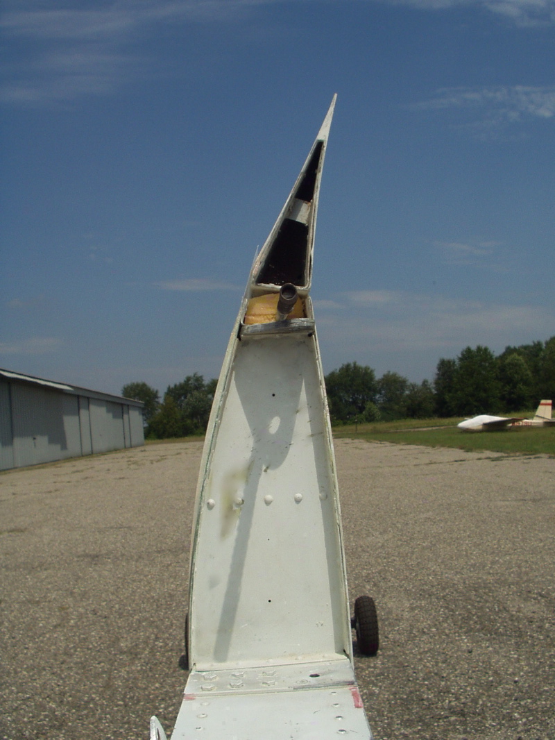
I used .014" mylar for the top seal on the flaps. A router was used to create a depression in the filler about 7/8" wide. I cut 3" wide seals from the mylar and applied it with no curve. However, a gentle curve would probably be better when the flaps are deployed much over +10 degrees for thermalling. Photo 8. shows the finished root end of the right wing. Note the thickness of filler on the top surface and the top mylar gap seal for the flap. The yellowish piece around the aileron push-pull tube is a foam seal stuck in place with 3M spray.
While I applied filler to re-contour the flaps to the new airfoil, I used no filler on the ailerons due to the concern of possible flutter. I believe the filler on the flaps is not a concern due to the relative stiffness of the wing in that area and lack of a degree of freedom (movement) compared to the relatively floppy aileron section of the wing. So far so good with speeds up to 120 mph in somewhat bumpy air.
So the ailerons needed relatively wide mylar seals to transition from the thicker wing section at the hingeline to the aileron surface. See photo 9. I also used internal cloth seals on the ailerons.
Photo 10. shows the finished product and also shows the nice seal that can be achieved between wing and flap/aileron.
The performance and handling of the glider so far has been a delight. A very preliminary and informal glide comparison with a LAK-17A showed about the same glide at 80 mph and at 100 mph the LAK was better, but not a huge difference. I don't mean to imply that my RS now flies as well as the LAK. It doesn't. But, it is a whole lot better than it was in stock configuration. Slow flight stalls are perfectly straight ahead and come with plenty of warning. I am flying this wing at 40% MAC and that seems to be where it flies best, at least for me. Perhaps it could go a bit further back. I started at 38% and then moved it to 40%.
The next step is to fabricate and install a flap/aileron interconnect so the full performance potential of this new wing can be realized. Then perhaps I can call my glider a "Super RS-15".
This has been a very rewarding project, although it is not for the casual tinkerer. The time commitment is significant. I must of course thank Udo Rumpf for his outstanding insight in creating this wing modification. Also, his encouragement and help provided during the project was extremely valuable and greatly appreciated. If anyone wants to discuss this project in more detail please do not hesitate to contact me.
Doug Hoffman
dhoffman@talkamerica.netAugust 26, 2005