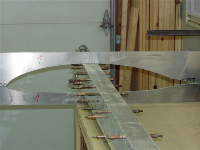
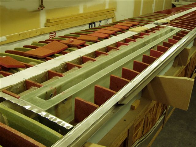
 Trial fit of the root template.
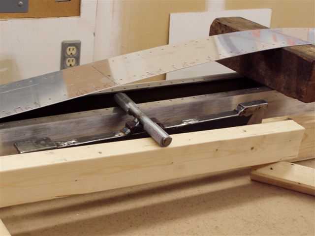
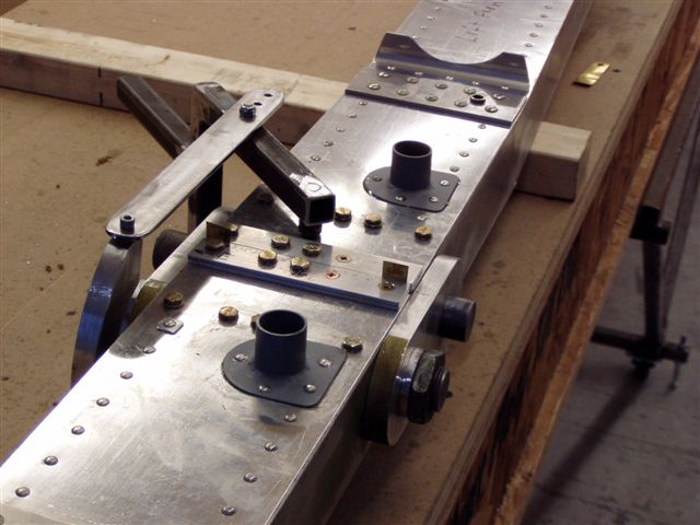
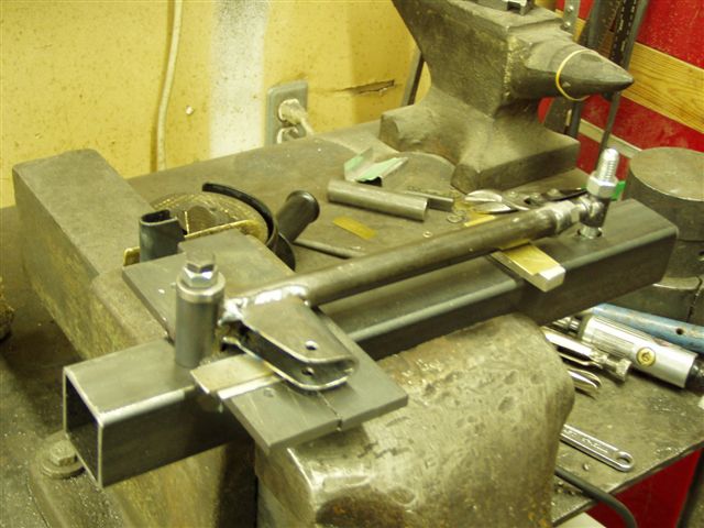
Bucking bar was designed by Jim Collins. The split PVC pipe on the rocking shaft protects the aluminum spar.
Udo riveting spar using Collins bucking bar. A plate was welded across the palm side of the bar to protect the hand.
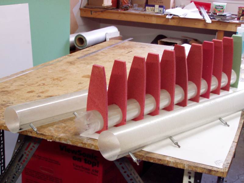
Cutting holes in foam ribs to accommodate water tanks.
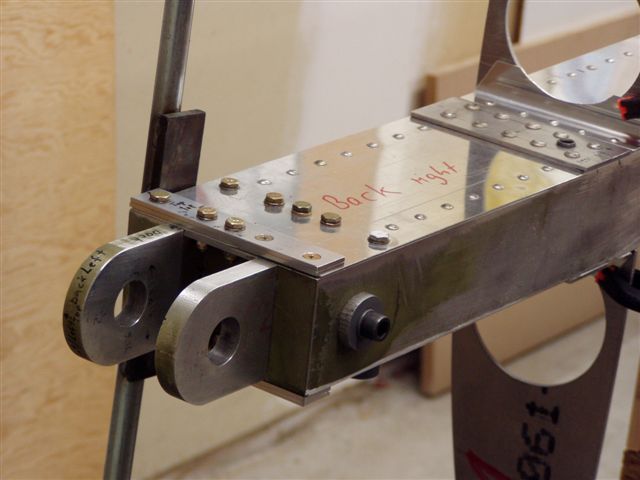
The Schreder pin has a .003" tolerance. The assembly pin has only a .0005" tolerance.
Checking total play of spar joint. The low tolerance assembly pin insure that the Schreder pin fits freely when all is done.
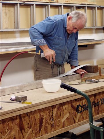
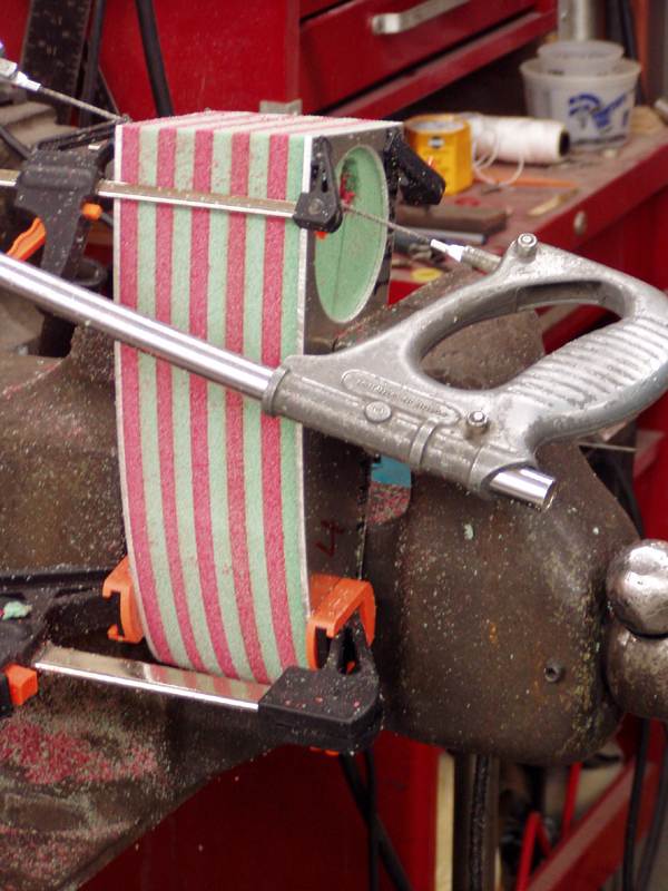
Making fiber glass water tank tubes.
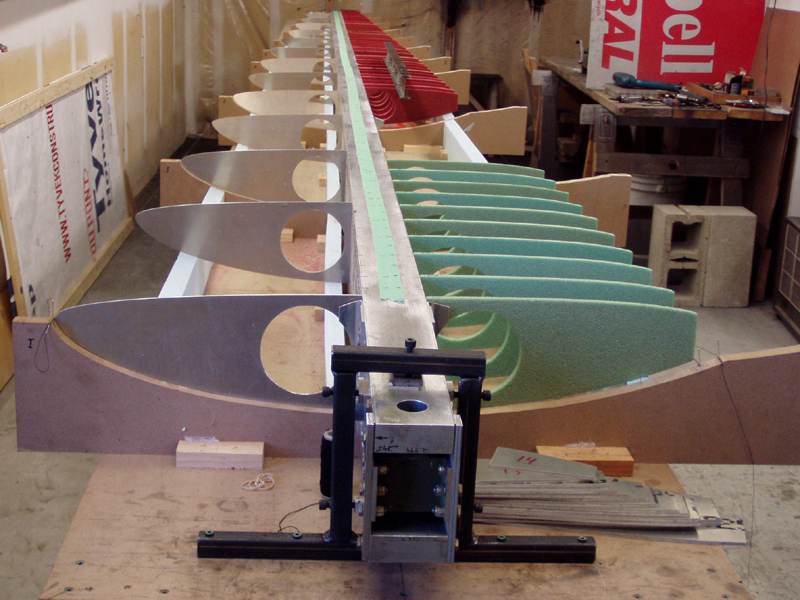
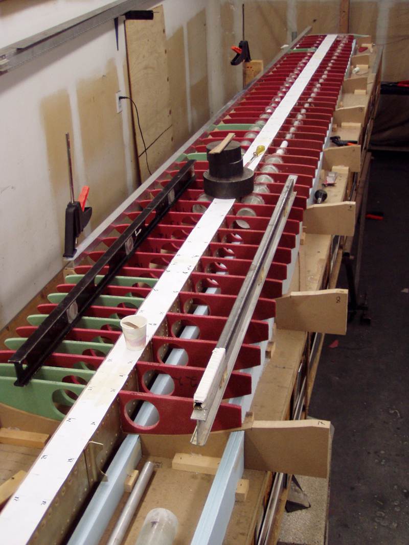
Adjustable spar holding jig. Well worth the construction time.
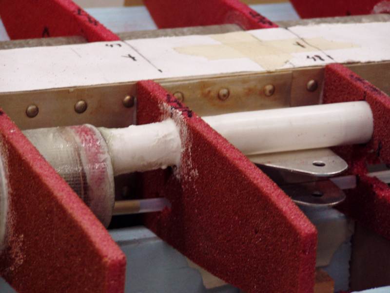
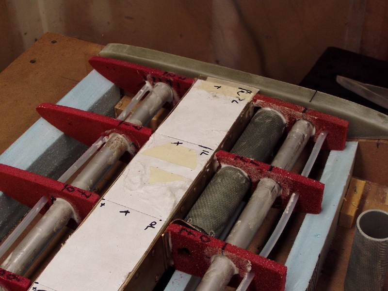
Installing water tubes in foam ribs.

View of wing tip rib showing water tanks, vents, and winglet spar receptor.
Wing tank and filler tube plus vent.
Plumbing terminal and winglet receptacle at wing tip.
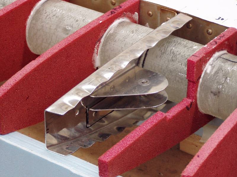
This metal rib in conjunction with a second one (not shown) will help box-in the spoiler box.

Spoiler Box Drawing.
(Updated April 9, 2006)
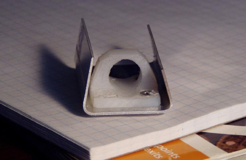
Small linier bearing made from HDP plastic. First drill hole then cut profile with band saw.
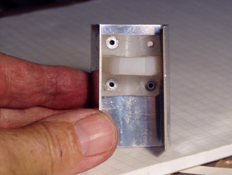
Top view of linier bearing.
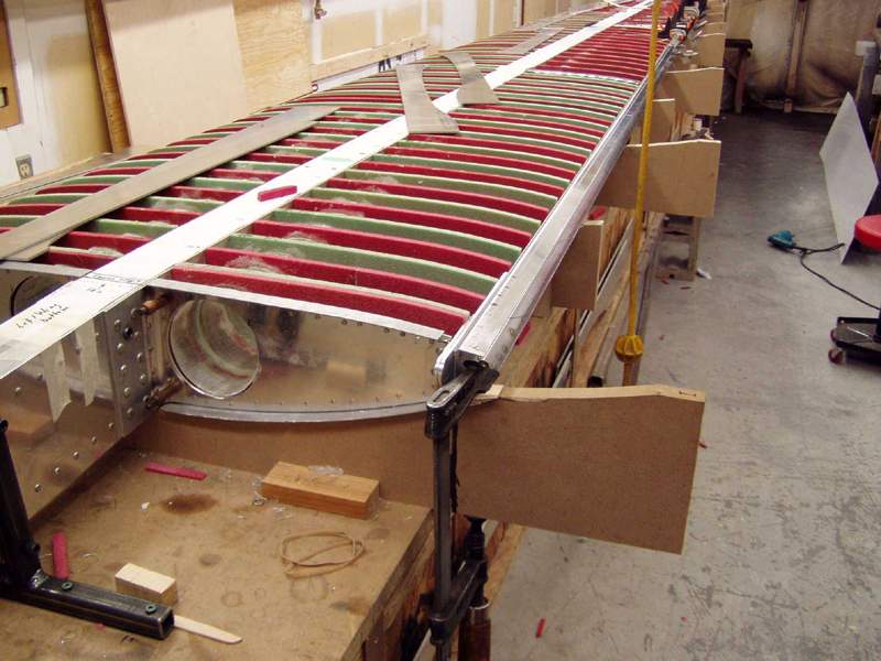
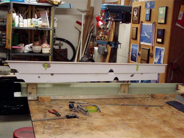
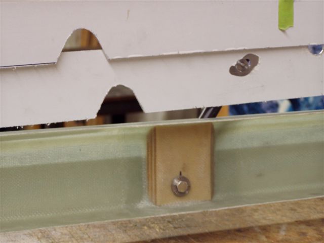
Rear spar installation
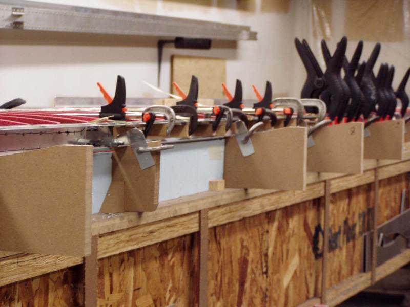 Another picture of the rear spar installation
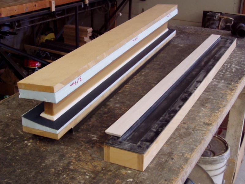
The mould on right side is for making the cap, on the left it is for making a one piece spoiler box .
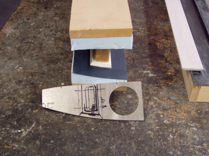
Note the relationship of the rib station ( it is upside down).
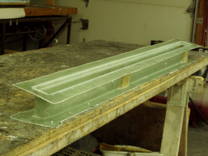
Spoiler box blank removed from the one time use mould.
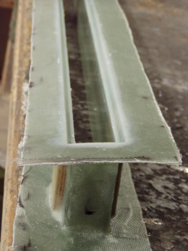
This view reveals the saddle for the spoiler cap.
Spoiler actuator arm
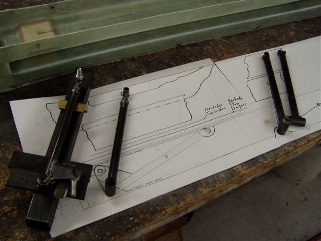
Spoiler drawing shown with actuator arms
Testing spoiler system
Actuator arm attachment point reinforcement
Spoiler Box in place waiting for glue