MAINTENANCE AND PROJECTS
By Les Sebald
Soaring June 1981 page 46-47
A TOTAL-ENERGY/VHF RADIO ANTENNA SYSTEM
Have you ever considered using your total energy probe for an antenna? Well, it can be done, and quite well, too.
Here is a Nicks tube T.E. probe (see Soaring, March 1977) that I am now using which pulls out to 24 inches for an antenna, stows away by just pushing it in, and does not require any disconnects. Above all, it works darn well as a T.E. probe, when used with a good gust filter, and is a superb antenna from 118-136 MHz. Its drag is estimated to be less than 1/10-pound at 60 knots. I am sure that this same scheme can be applied to other types of T.E. probes.
|
|
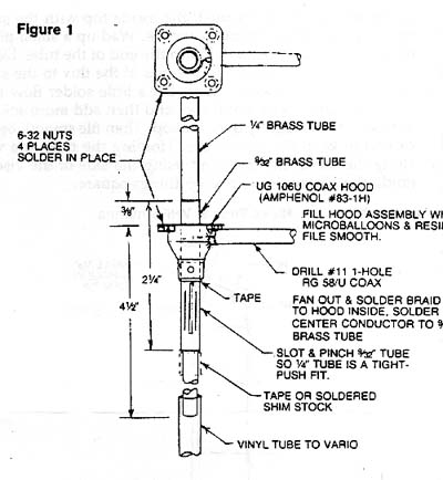
To build a unit, refer to Figure 1 and start with the hood as shown. This mounting device is made using a standard coax cable fitting UG-106/U hood. The Amphenol Company carries this part as 83-1H. Most radio stores handling coax parts, except Radio Shack, should be able to help you locate one. If not, you may be able to bend up something like a hood from some thin brass stock that will provide the coax termination and mechanical support required. To make it easy to install later, solder some nuts to the underside of the flange hole area. Next drill a #11-drill-size hole for the coax through the side of the flange. Dress the end of your RG-58/U coax cable, so that the center wire extends about 3/4 inches and the braid wire about 1/4 inch. Clip the center insulation back to near the base of the braid wires. Tin the inside of the hood near the #11-drill-size hole. I use "Ruby Fluid" flux, but any good flux will make the solder flow smoothly. Insert the prepared coax into the hole and fan out the braids. Carefully solder them to the inside of the hood. Treat coax almost like it must hold water and you will not be so susceptible to RF leaks down the outer braid and into your mike and vario systems.
|
|
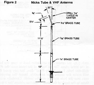
From your local model or hobby shop, procure a brass tube that will nest your T.E. probe. Cut a 2 1/4-inch length of the tube and slot it as shown in Figure 2. I cut the slot with a Dremel tool and small saw blade. Deburr the inside and gently pinch the tube near the cut so that the 1/4-inch tube will nest inside with an authoritative push. Wrap a small piece of tape around the 2 1/4-inch tube as shown, and fit it snugly into the hood flange. After tinning, solder the center coax wire to the tube. Fill the hood with resin and microballoons if you have any. Be sure that the tube is straight and upright before the resin sets. When cured, file the resin at the top for a flush fit to the fuselage.
If you don't already have a total energy probe that fits into the holder and is long enough to be an antenna, you may make a Nicks tube as described by Oran Nicks (Soaring, March 1977) and by referring to Figure 2. Procure four nesting 12-inch lengths of brass tube from 9/32 to 3/16-inches in diameter, When joining the brass as shown, use solder flux and tin the sections before joining. I make the top 3/16-inch diameter tube by first filling the tube with sand and packing down well. With the aid of my navigational plotter scale and a 1-inch round pope held in a vice, I carefully bent the brass tube to the 20 degree angle specified at a point about 3 1/2 inches from the end. Ease the bend carefully so as not to cause a kink.
|
|
Clean out the sand. Next, mount the tub bend in a vice so that you can sight along the top of the vice jaws and thus establish the forward centerline of the tube. Hold it gently. I made a pencil mark on the centerline and, after measuring down 3/8 inches, made a small prick into the brass with a sharp prick. To drill the hole, use a brand new, very sharp 1/16-inch drill held in a pin vice or small hand drill. This takes practice to get the hole in the center as required. Once drilled, deburr and polish using a fine grade of steel wool. This will also burnish the edge of the hole. Burnish the inside top with steel wool and tin down about 3/16 inches. Wad up a small piece of steel wool and push it into the end of the tube. Add a few drops of the flux to the steel wool and then fill with solder. Let a little solder flow first to make a good dam. Let it cool and then add more solder. Build it up and slightly over the top. Then file smooth being careful to keep the top square. Holding the tube in a vice along the top of the jaw and using a side of the vice to guide the file might help keep things square.
|
|
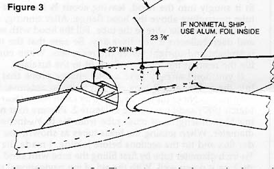
Figure 3 shows how I mounted my unit. It should be 1/4 wavelength (about 23 inches) back from an edge, as shown. If your ship is not metal, attach some heavy-grade aluminum foil inside the glider to form the ground plane. It is not critical, but try to extend it out from the base of the antenna about 23 inches in all directions if you can. Once installed, the antenna may be extended 23 7/8 inches and a small tape or soldered shim stock used to prevent pulling the tube too far. See Figure 1. Attach the vinyl tube to the rest of the vario system and the coax to the radio and check for leaks. Allow enough vinyl tubing so that the Nicks tube can be pushed into the ship out of the way when not in use.
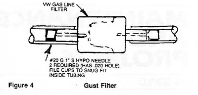
To get my Nicks tube to really perform with my Ball vario, I gave up on electric dampening and added a gust filter which prevents the problem in the first place. See Figure 4. This may not be the best filter in the world, but it seems to have a very nice response and is practically of the shelf. The VW gas-line filter makes a nice dust filter and all for $1.15. The restrictors may be obtained through usual sources or duplicated using other means.
|
|
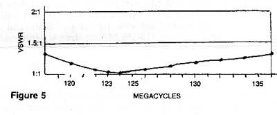
For those who may be interested, Figure 5 shows the antenna voltage standing wave ratio measured on my ship. This is very good, indicating that nearly all of the power is being radiated and virtually none is being reflected back to the transmitter.
Note: A quarter wave antenna on 123.3 MHz using tubing of this diameter should come out to be very close to 23 inches. This antenna came out 7/8 inch longer than might be expected probably due to the effects of the protruding section where the vinyl tube connects.
This article is courtesy of Bob Kuykendall. Bob has made a half-dozen or so kits for this assembly. His kits include a machined aluminum base that replaced the (now unavailable) formed brass UG-106U connector hood: his machined part included a bayonet style connector instead of Les's permanently-attached coaxial cable. He still has many parts left over, including several pre-bent and pre-drilled Nicks tubes (just the part at the end) and several machined mounting bases. He may be contacted at (408) 495-3489 if you have any questions.