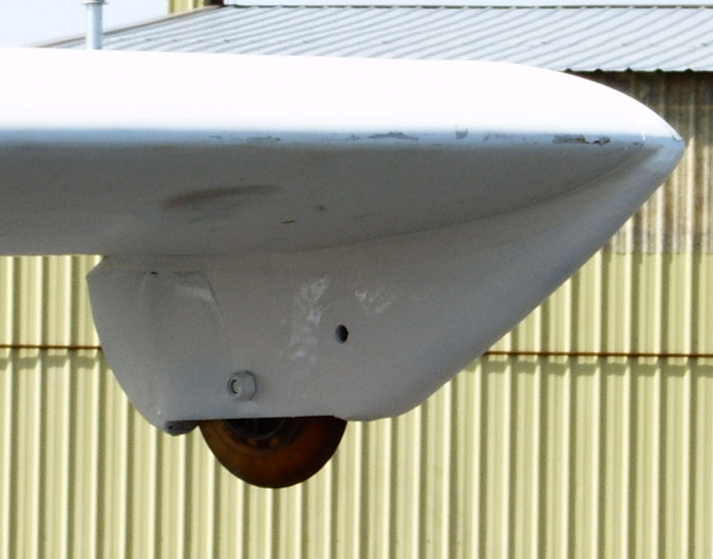
Overview
Spacing
Offset
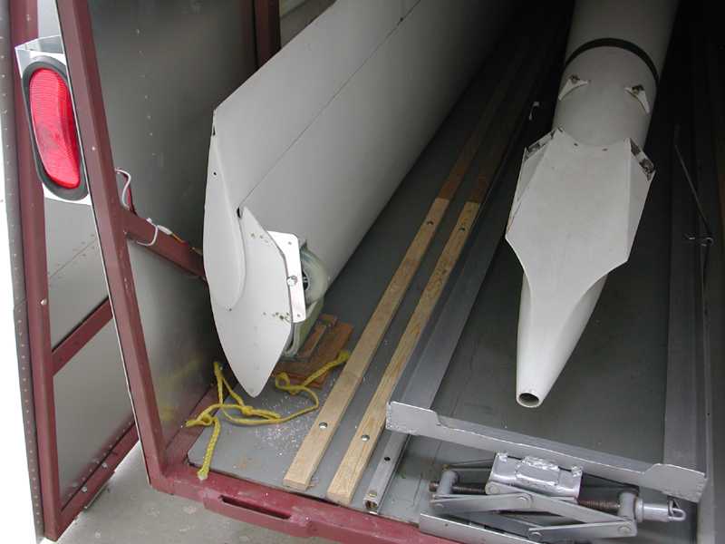
Trailer
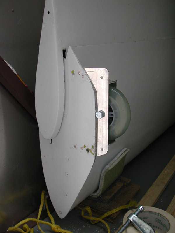
View One
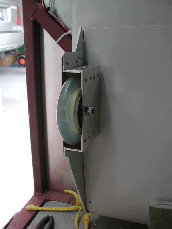
View 2
Crude but Functional Wing-tip
Wheels
by
Wayne Paul
Our local airport, as well as the majority of airports from which I will fly, have paved runways. This as well as the low aileron clearances necessitate the installation of wheels on the wing-tips.
I have previously installed tip wheels on an HP-16. In that installation I used "in-line" skate wheels. I still have several sets of bearings and axles; however, no wheels. The local sporting goods stores only sale roller-blade/in-line skate wheel in packages of eight. I really didn't want an extra six wheels laying around. While walking through Wal-Mart I noticed scooter wheels on sale. These wheels are approximately four inches in diameter. (Installing scooter wheels will provide a little over two inches of extra aileron clearance.)
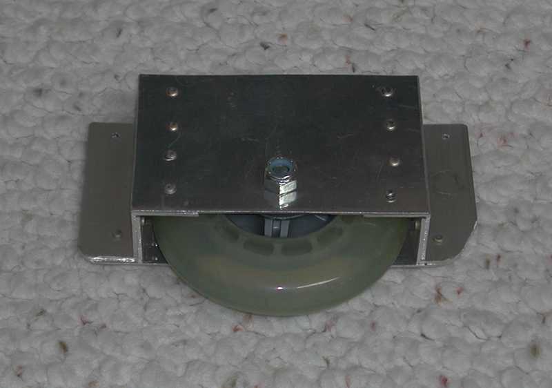
After measuring the clearance on the inboard side of the wing-tip plates it became apparent that inboard installation of either roller-blade or scooter wheels would require the wheel axle to be below the lower edge of the wing-tip plates. Either solution require the creation of some kind of a wheel well box. After looking around my shop's scrap pile, I derived a solution which involved items that I had on hand. The materials include one inch 6061-T4 angel and .050 2024-T3 sheet stock. There was no engineering in the selection of these materials. They are simply what I had immediately available.
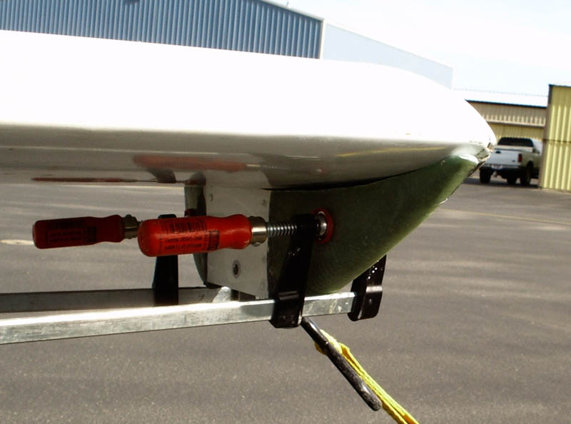
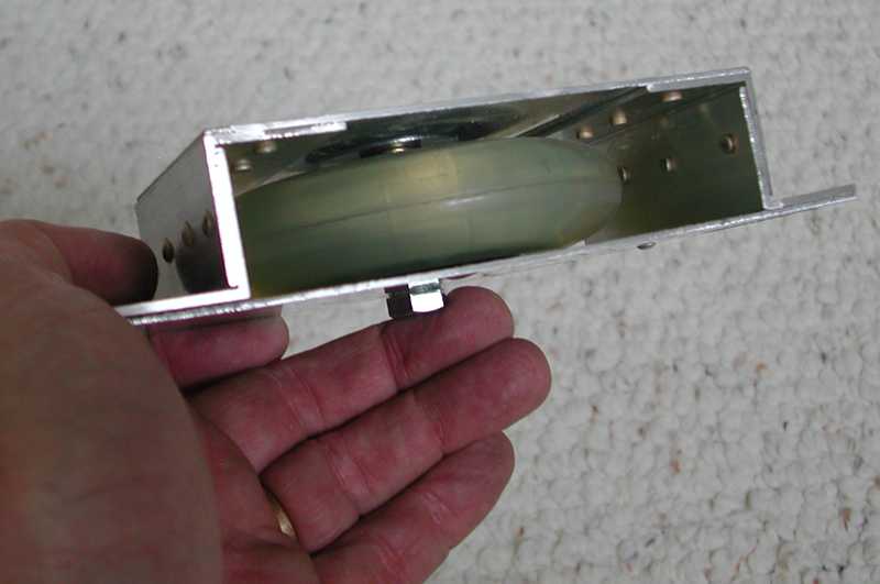
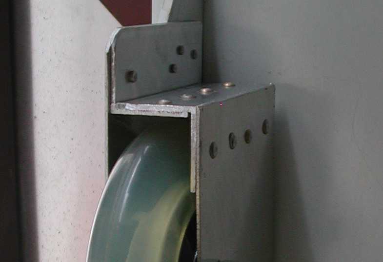
The first step was to cut the 1" angle into eight 3" lengths. (Four for each wheel well.) Next a spacer was created to allow for the thickness of the wheels. One section of angel was c-clamped to a piece of plywood the mating piece of angel was clamped in position separated by the spacer. (See the approximately .060" offset created by the spacer in the "Offset" photo below.) After drilling the first hole, I inserted a cleco to ensure the pieces did not move while drilling the remaining rivet holes. This is the only critical part of the project that requires explanation. The 4 1/2" by 3" plates drill and riveted to the inboard angle faces. Only one rivet is fastened to each end of the 6 1/2" by 3" plate. These rivets fall below the lower edge of the wing-tip plate and can be seen in the "Overview" picture. Finally to the drill press to drill the axle holes.
|
Overview |
Spacing |
Offset |
Trailer |
|
|
View 2 |
||
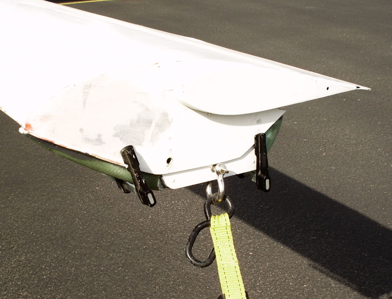
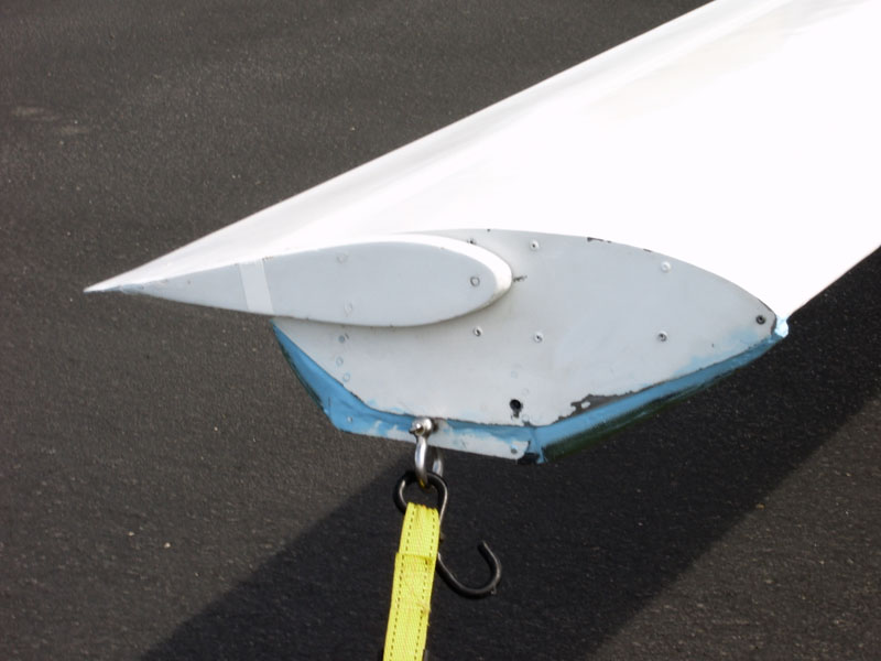
Finally drill and rivet the wheel wells to the wing-tip plates. As is stated in the title, this is a crude but functional wing-tip wheel solution.
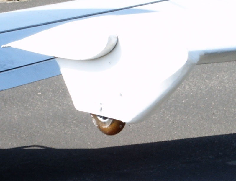
Fairings Added
After flying the configuration pictured above, Brian Case suggested the addition of fairings. I took his advice, and a bit of his foam.
It took three layers of this foam make a block the thickness of the wing tip wheel box. The three layers of were glued together using Loctite 9460. Shaping was accomplished using a sanding block with 220 grit paper. Once shaped the foam was covered with four layers of fiber glass. (I don't know the weight, it was scraps I had stuffed in a box. It is bidirectional cloth. I think it is Rutan 8.8 oz cloth.) The glass was applied on the bias and wetted with Poly Epoxy.
The inside of the root plates were prepared by removing the paint and scrubbing with a scottbright pad. The fairings were glued (using Loctite 9460) to the tip plates and wheel boxes avoiding getting glue on the bottom wing skins.
Once the glue dried tie-down holes were drilled through the foam and fiberglass. A large washer was then glued on the backside of each fairing to distribute tie-down pressure. Poly-Fiber Superfil was used to make a smooth transition between the tip plate, wheel box and fairing. It took three applications and sandings to develop smooth transitions.
Finally the tip plates were painted with Toyota 040/HP bright white paint. (If you look closely in the last picture you can see the washer.)
I doubt the fairings will improve performance; however, it sure looks better.