WING
The HP-18 is a well conceived home built design. I felt confident, however, that I would be able to raise the performance and comfort levels substantially.
Firstly, I focused on the wing. It is well known that the FX-67 k 170 have their limitations vs. today's standards. Even if the HP-18 wing is precisely contoured to the exacting standards that are required to extract the maximum performance from that airfoil, the effort invested would not show results that would be satisfactory.
My goal was to design an airfoil that fit around the existing wing structure and still meet my requirements for a modern airfoil that would have excellent climb performance, extended laminar flow on surfaces and yet not be too sensitive to contamination.
With the aid of my ACAD I assembled all recent, published airfoils that had adequate wind-tunnel data or well substantiated empirical data. I reviewed publications of Eppler, Horstmann & Quast, D. J. Marsden, Boermans, G. Waibel, Peter Masak and R. H. Johnson. It was interesting to note, when layering modern airfoils, starting with the ASW 20, that all these airfoils had similar velocity distributions on the top 50% of the airfoil, except for the FX-79. Based on my own insight and the excellent data of Dave Marsden, my choice was Marsden's UAG88-143. This airfoil had near-perfect fit from the leading edge, the top surface and the intersection of the rear spar onto the flap. The HQ-17 was used for the bottom surface because it too had a good fit. The flap on the HP-18 has a poor fit and too much under camber and I intend to replace mine sometime in the future. Once the airfoil was assembled onto the screen, new coordinates were stuck and a new airfoil, with a thickness ratio of 15.3% and a camber of 4.5% emerged.
|
|
The wind tunnel data of the UAG88 reveals a minor improvement with a turbulator located at 64% on the top surface at low Reynolds numbers. My experience shows that with the now modified airfoil (for the purpose of identification let's call it UDO 15.3-93) with the turbulator at 60% on the upper surface and a flap setting of 8 degrees and high CL, the turbulator is very effective. On the bottom surface I used the 75% placement which has proven itself to be a very good compromise based on other experiments with the HQ-17 airfoil.
The rear of the root fairing was changed to provide a more streamlined transition as well as longer wing-fuselage fairing.
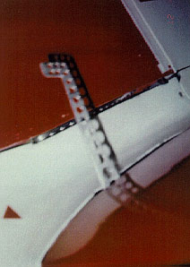
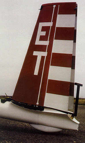
WINGLETS
Due to the constraints of an existing wingtip and trying to stay within the 15 metre wingspan it posed a challenge to design an effective winglet.
A winglet kit provided by Ed Hollestelle was assembled, based on the well established criteria set out by Peter Masak. However, in test flights, I discovered that the bottom surface in the region near the wingtip (aprox. 10 inches) had extensive separated flow.
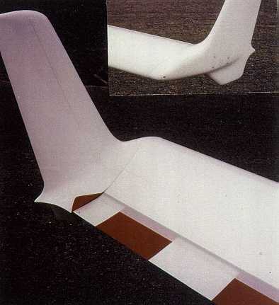
The solution was to cut approximately 4 inches of the aileron tip and provide a stream lined transition that corresponds to the maximum negative flap position. Combined with a small aileron fence and a reduced skid size, a more orderly flow now exists on the bottom. The winglet turbulators were conservatively placed to ensure attached flow.
Nevertheless, the desired wraparound flow is impeded by the skid plate. The corner that is formed by the leading edge and the tip causes airflow roll off at all speeds which has a negative effect on the total flow around the winglet, especially at higher speeds.
But the winglets are beneficial throughout the flight regime and I would not fly without them.
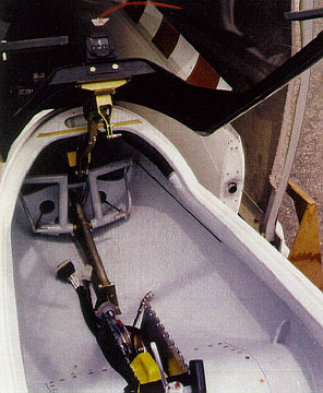
CONTROLS
I used a PIC20 control stick. Only minor modifications were necessary to fit the assembly. The pushrod routing was direct, only the elevator/acuator on the mixer was mirrored and the pushrod arm was modified. A new aileron bell crank with more differential and throw was designed. The results were 25 degrees up and 12.5 degrees down between 0 flaps and plus 15 degrees of flap.
After the wing and winglet were completed, I tested the original aileron size which was now adequate even without the winglet. The best compromise was to add 20 inches of the flap to the aileron. With the winglet, the plane is now very responsive and a pleasure to fly. On takeoff the c/g tow hook is used with 8 degrees of flap. The HP-18 can now be flown in a 2 point position off the ground with no wing drop -- behind a tow plane of modest horsepower -- contrary to takeoffs with modern ships where negative flap is used for the initial take off roll.
The trim is a fingertip control arrangement. Only two trim settings are required. One for landing and takeoff the other on for all other normal flight conditions. The flaps takes care of all other trim needs.
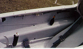
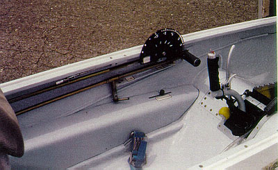
COCKPIT
The cockpit modification, was an effort between Terry Healy and myself. It required changing the top of the fuselage, from the nose to three feet past the trailing edge. Terry offered to make the molds while I focused on anther aspects of the conversion. He also was the man with the most experience in canopy making.
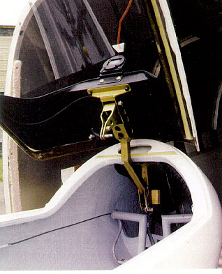
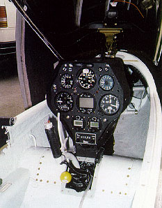
The one piece canopy is hinged at the front and has an emergency release, which is actuated in front of the instrument panel. The instrument panel is generous in size, due in part to the 32 inch high cockpit seating. The instrument cluster can be removed in seconds. The vent, the seatpan adjustment and water ballast release are all placed, conveniently, on the right hand side. The flap crank had to be moved forward due to the new seating position.
CONVENIENCE FEATURES
The two V-Tail surfaces each have a retractable, single lever inline taper-pin actuator that is conveniently operated from the top. No more pulling the pin off line out of the tapered hole on the bottom. A six inch fixed tail wheel is installed to provide better directional control. All wing-pins and aileron connections are self-securing and locking. Tem main wheel received a hydraulic disc break. Up front a generous air intake provides ventilating air to the front and side vent. The vent is an integral part of the cockpit rail.
PERFORMANCE
After a number of test flights with tows in the early mornings up to 5000 ft., flying through a measured distance, it was determined that the plane had a L/D of not less than 43:1 @ 57 kts. with a wing loading of 6.9 lbs./sq. ft. Subsequent comparison flying confirmed the performance. After twelve competition days, in three different contests last year, the evidence was in -- the climb performance was outstanding. At higher speeds (starting at about 90 kts), the verdict is not in because I have been unable to fly comparison tests with equal wing-loadings. I am flying with a LX 4000 final glide computer with the ASW 20 settings and it appears to be a good match. I had feedback from SZD 55 and ASW 20 pilots who confirmed the excellent performance of the modified HP-18. The only thing left is to give the owner/pilot a "makeover."