BUILDING THE HP-18
PART TWO
By Richard Schreder
This installment of the "Building the HP-18" series will reprint much of the information we send along with the kits to the homebuilder. As promised, it explains the steps in putting the V-tail together. I am frequently asked why either a T or C (conventional) form was not chosen for the HP-18, so perhaps it would be well to begin with an explanation. I have tried T and C tails on other sailplanes, but for the homebuilder I believe the V-tail is superior for the following reasons: Lightness; Strength; Fewer parts; Easier to build; Less drag; Simple to fold; Less susceptible to damage in rough terrain; Easy to counterbalance; Eliminates trailer stowage of removable parts; and, Eliminates hazard of disconnected controls.
The one disadvantage of V-tails is weaker directional control during takeoff and landing. This characteristic is completely eliminated by locating the 5.00 x 5 main wheel ahead of the cg, and by connecting steering cables directly from the adjustable rudder pedals to the shock-absorbing tail wheel. This arrangement gives the HP18 superior ground control regardless of tail types. The tail wheel swivels 90 degrees and allows the pilot to pivot the sailplane and push it with wings level without additional help. The pilot can also make precision turns off a runway at any speed after landing.
Before getting into a step-by-step description of building the tail surfaces, the reader should study the following general notes on certain procedures, precautions, problems, and practices. Some of these (e.g. notes on the landing gear, wing straps, aileron and flaps, etc.) will apply to future installments, and the reader should keep them handy for future reference:
Avoid scratches and nicks: Do everything you can to prevent scratching aluminum sheet, spar caps, angles, tubes, etc., because such damage weakens structural members and concentrates stresses which can initiate cracks. Remove such scratches or nicks from highly stressed areas with emery paper or file.
Corrosion prevention: Always paint bare steel, 7075-T-6 aluminum, and magnesium parts to prevent corrosion except where glue must be applied. Main spar caps are extremely vulnerable to this form of damage if they are not properly protected.
Cleaning aluminum: Aluminum must be properly cleaned and prepared for paint and glue. A single fingerprint can deposit enough oil to prevent adhesion on any surface. The recommended treatment for aluminum is to first remove all traces of ink, oil, fingerprints, and dirt with MEK (methyl ethyl ketone), acetone, or lacquer thinner on paper toweling. Don't use shop towels as they are cleaned with solvents that contain oil. The second step is to remove aluminum oxide and the glossy finish by brisk rubbing with dry Scotchbrite pads. These are available at grocery stores and industrial supply houses. The above cleaning procedure should be repeated whenever cleaned surfaces have been touched with bare hands or when cleaned surfaces have been exposed for more than three hours.
Drilling rivet holes: A steel drill guide with twenty-four 1/8-inch (#41) holes spaced on one-inch centers is furnished in the kit to simplify drilling straight, accurately-spaced holes. Paint one end with colored paint on one side so that guide can be properly oriented when exact matching of holes is desired. Holes should be free of burrs and chips.
Attaching hinges: Mark piano hinge locations on rear stabilizers and wing spars so that skin rivet holes are centered on each finger of the hinge. One-half inch strips of double-faced carpet tape will hold hinges in place until they can be clamped and drilled through appropriate skin rivet holes. Hinges must all be in line so that flaps can operate freely. Stretch a long string to check overall straightness. Recheck alignment of each set of flap section hinges with a four-foot straightedge before drilling. Number all hinges so that they don't get mixed up. Predrilled matching hinge sections can be temporarily attached to stabilators, flaps, and ailerons by holding the control surface section in place on the wing or stabilizer to mark the exact location of hinges and then taping them in place with two strips of 1/2"-wide masking tape across the gaps between fingers. The tips of the fingers should be set in .065 inch from the skin surface on flaps and ailerons and .088 inch on ruddervators. With three hinges thus attached, the fit can be checked and if okay drill through the holes already in the hinge sections fastened to control surface. Remove hinges, clean out chips, replace, and pop rivet with MD 419 BS rivets.
Riveting: Three-sixteenth inch diameter rivets can be driven just about as well with a hand hammer as with a rivet gun. This size is only used to hold fittings to inboard ends of front and rear wing drag spars and main stabilator spars. Clamping the rivet set in the vise, placing the rivet head in it and hammering the shank end of the rivet seems to work best. Double check all rivets to see that I to 11/2 of the shank's diameter extends through the metal plates being riveted to give a properly sized head when driven. Heads will be too small if the free length is less than one diameter and too large (or they will bend over) if more than 11/2 the diameter. Use the following drill sizes for rivets:
|
3/32" |
#41 |
|
1/8" |
#30 |
|
3/16" |
#12 |
|
7/64" (MK 319BS Pop) |
#35 |
|
1/8" (MK 419BS Pop) |
#30 |
Bolt position and length: Heads should be up or forward unless application dictates otherwise. No threaded portion should ever be loaded in shear, so be certain that full shank diameter extends through such fittings.
Nuts: Self-locking types are used where they can be drawn up tight. Cotter-locked castellated style are used where rotation is involved or nut cannot be drawn up tight.
Pop rivets: Be sure to use the proper size for the thickness of metal being fastened. A table of grip lengths for various sizes follows:
|
GRIP LENGTHS |
||
|
Rivet No. |
MD (Dome Head) |
MK (Countersunk Head) |
|
319 |
.020 - .070 |
.020 - .090 |
|
419 |
.020 - .070 |
.030 - .100 |
|
424 |
.071 - .120 |
.101 - .150 |
|
429 |
.121 - .170 |
.151 - .200 |
|
435 |
.171 - .230 |
.201 - 260 |
|
440 |
. 231 - 280 |
.261 - 310 |
Monel metal pop rivets are used where blind riveting is necessary and solid AN 426 or AN 470 aluminum rivets where there is no bucking problem. Pop rivets are usually stronger than aluminum rivets but are not used 100% because they are ten times more expensive, heavier, and leave a stem hole that must be filled to get smooth watertight exterior surfaces.
Washers: No washers are used under bolt heads unless more bearing area is needed in soft material. One washer is normally used under a nut to prevent scoring when the nut is turned. Two washers can be used if bolt is too long. More than two washers is considered to be poor practice. Use a shorter bolt instead. At least one full thread should show above the nut but not more than three threads.
Venting and draining: All interior compartments of wings, flaps, ailerons, stabilizers, and elevators formed by ribs, spars, and skins must be vented with bottom drain holes (see drawings for locations) to allow interior pressures to equalize with outside pressures during climbs and descents. Failure to provide such pressure escape routes could result in destructive explosion or collapse of structural components during flight. These vents are formed by filing 1/4 "-deep notches in foam ribs in appropriate places. The vents provide an additional function by providing drainage routes for moisture. Trapped water or ice in movable control surfaces could induce violent flutter characteristics.
Wing skin straps: Fifteen 2"-wide straps with quick-release buckles are used to hold wing skins in place for drilling rivet holes. Special straps for this purpose can be obtained from Bryan Aircraft on a purchase-return basis.
Mixing glue: EA 9410 adhesive must be mixed in the ratio of 100 parts A to 22.4 parts B by weight. The sketch above shows how to make a simple balance scale that will properly proportion any amount of adhesive. E is a 3/8" x 3' x 32" board with pencil lines drawn across the top at points A, B, and C. F is a fulcrum glued to the wood so that it will stay in position under line C. Center a paper cup on line B and another of larger size on line A. Balance the entire assembly by placing a convenient counterbalance weight at position D (this will vary according to the size of the weight and paper cups). Add part A epoxy to cup A. Pour part B hardener into cup B until scale balances on its fulcrum F. Be sure that all parts to be bonded are properly cleaned, rib locations in control surfaces are properly marked, and that everything is in readiness before the hardener and epoxy are mixed. Measure only enough to do the job at band as per the estimate below:
|
QUANTITY (before adding hardener) |
||
|
ITEM |
Top Surface |
Bottom Surface |
|
Flap or aileron |
1 to 1 1/2 oz. |
2 to 2 1/2 oz. |
|
Wing, inboard |
40 oz. |
28 oz. |
|
Wing skin splices |
1 oz. |
1 oz. |
|
Ruddervators |
1 oz. |
2 oz |
|
Stabilators |
1 oz. |
1 oz |
|
Front and rear fuselage joint (complete) -- 2 oz. |
||
Mixing glue: Epoxy should be thoroughly mixed so that uniform cure will be obtained. Glue should be applied to structure as soon as possible after mixing, because heat given off after combining A & B parts will build up and accelerate the curing rate of quantities confined in cups or envelopes. This means that all EA 9410 must be spread within twenty minutes and closure of parts to be completed within forty minutes at 80'F room temperature. Lower temperatures will extend these values to thirty and ninety minutes respectively at 60'F. Do not chill epoxy to prolong pot life, as application in a warmer room could cause moisture condensation on the cement which would prevent adhesion. Small quantities should be mixed and applied from a small cup. Wing-skin quantities should be mixed and poured into a 30/60-degree triangular polyethylene envelope furnished with the kit for this purpose. Close the envelope with a twisted wire bag tie strip and snip off the tip at a point where it is 1/4" wide inside. Squeezing the bag will then extrude a bead of glue about 3/16" in diameter.
Landing gear maintenance: Shock struts should be kept clean and oiled to prevent rusting. Pivot points should be oiled. Struts are filled with red hydraulic oil when pistons are 1/2" from touching bottoms of cylinders. Struts are then pumped up with a strut pump or compressed nitrogen so that they are just fully extended with the ship loaded for takeoff. Approximately 400 psi will be required.
Control surface settings:
|
Rudder |
15 degrees right |
15 degrees left |
|
Elevator |
15 degrees up |
10 degrees down |
|
Total Ruddervator movement |
30 degrees up |
25 degrees down |
|
CG travel |
15 to 40 % |
Of mean aerodynamic chord |
Tolerances: Make and fit parts as accurately as possible. Good appearance and performance require careful attention to detail. Nothing looks worse than twisted or wavy surfaces, so check and double check your work to avoid spoiling components.
Control surface gaps:
|
Between flap sections |
1/8" |
|
Between aileron sections |
1/16" |
|
Between flap and aileron |
1/16" |
|
Cover above joints with 1" wide white vinyl tape. |
|
|
At end of all surfaces |
1/16" |
|
At wing root to fuselage |
1/16" |
|
At stabilator to fuselage |
1/16" |
Fill the following ribs with epoxy-glued Styrofoam blocks and sand smooth:
a. Inboard end of no. I flap. Outboard end of no. 4 flap.
b. Both ends of ailerons.
c. Inboard ends of ruddervators.
d. Outboard ends of stabilators.
e. Stabilator fairings.
Lubrication: All pivot points should receive a drop of light oil each season or every 100 hours. The same treatment should be given to all parts that move on each other. The exceptions are piano hinges and metal riding on plastic bearings like Nylon and Teflon. Oil or grease can collect sand and dirt on such bearings to cause excessive wear or jamming.
[Ed. note: Not mentioned here is Dick's policy of making refunds that run from 50% to 100% for special tools such as tapered pin reamers (for use on stabilator fittings), 24-hole drill guides (spaced on one-inch centers), and 2" x 6" wing straps with quick release buckles. He also makes available hydraulic pop-rivet guns, epoxy kits, polyethylene, envelopes, and PVC loam at low prices.]
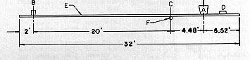
If you've studied the plans on these pages carefully, you have undoubtedly noted the absence of some detail dimensions. This is because we don't expect the builder to do the layout work, and in the kits some parts are scribed while other more difficult units come already welded, machined, drilled, threaded, bent, and heat treated. There's still plenty for the homebuilder to do because FAA regulations require that the "major part" (this is generally interpreted as at least 50% ) be done by him. This is why it isn't possible -- as was mentioned last month -- to build an HP-18 from scratch even with the detailed drawings and instructions in this series. But Soaring tells me that its readers keep asking for homebuilder articles with details-with "nut & bolts" particulars-of what goes into the making of a modern high-performance racing sailplane, and that's what this series is trying to provide.
We usually recommend starting with assembly of the tail surfaces first because they are simpler, smaller, and give the builder a chance to work into the larger and more complicated items after he has built up some experience.
If care is taken, considerable time can be saved by building both stabilizers and rudder-vators in parallel with one another. This permits more efficient use of tools, mixing of glue, and assembly procedures.
Ready? Let's go. Here are the 27 steps contained in the instructions for building the stabilizers:
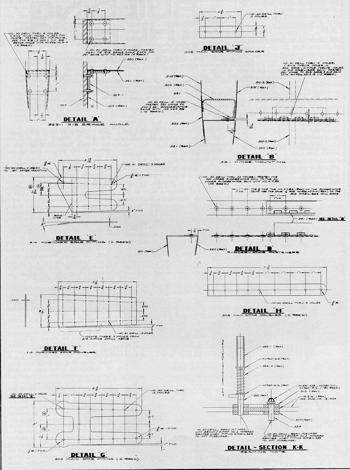
1. Check stabilizer spars against the drawing for proper length. Trim and square off ends as necessary.
2. Cut and file front and rear spar fittings.
3. File the rear main spar fittings to fit the inside spar flange radii.
4. Clamp and drill fittings, spacers, and spar using a No. 30 drill. Make sure that holes pass through spars and fittings as illustrated in drawings.
5. Clamp root rib in position on main spar and run drill through spar holes and rib flanges.
6. Ream out all holes with No. 12 drill, clean chips, and rivet. (3/16" rivets may be hand driven by resting rivet head in set clamped in vise and hand hammering shank end of rivets as explained previously).
7. Clamp front spar fittings to front spar and drill with No. 30 drill bit.
8. Clean out chips and rivet all holes except those attaching spar to root rib.
9. Clamp root rib in place, run drill through fitting holes and rib flange.
10. Remove chips, reassemble, and rivet.
11. Clamp tip rib in place, drill, clean, and rivet.
12. Trim foam stabilizer ribs and sand to lines.
13. Clean inside areas of spars for gluing to foam ribs.
14. Glue ribs in place. Use masking tape to hold them in position. After glue has set up, check contour of foam ribs by use of a 4-ft. straightedge placed radially on tip and root ribs to simulate skin. Sand down any high spots on foam ribs that would not allow skin to lie flat. Notch lower rear corner of ribs for drainage as explained earlier.
15. Place pre-bent stabilizer skin on floor with a I" x 4" x 4' board on skin at leading edge. Press down on board to flatten bend so that spar and rib assembly can be installed; a perfect fit will result when rear edges are held against rear spar. Avoid placing too much weight on ends of board because ends of skin will bend easier than center. Rear edges of skin should be about 8" apart at root and 6" apart at tip when bent skin is laid on a fiat surface.
16. Clamp skin to structure so that all parts are covered when the rear spar web makes a 90-degree angle with the root rib web and there is 0-degree twist in the assembly. Also check the leading edge for proper overhang as per drawing at root and tip as well as perfect symmetry about the chord line. 0-degree twist can be verified by taping narrow straightedges to the root and tip rib centerlines and twisting the stabilator until the straightedges sight parallel.
17. Drill No. 41 skin rivet holes in the following order:
a. Top rear spar Range
b. Root rib top flange
c. Tip rib top flange
d. Top front spar flange
e. Bottom front spar flange
f. Bottom root rib flange
g. Bottom tip rib flange
h. Bottom rear spar flange
(Frequent checks for freedom from twist during this drilling will ensure a perfect finished airfoil.)
18. Trim skin on top of rear spar so that it is even with the aft edge of the flange. File as necessary to get this edge absolutely straight.
19. Clamp extruded hinge sections in place so that hinge pin centerline is directly under the aft edge of the spar and the fingers are centered on the appropriate holes. Drill through with a No. 41 drill bit.
20. Remove skins, clean out chips, countersink holes in spar flanges, and dimple skin and rib holes.
21. Clean inside areas of skin where it will contact foam ribs.
22. Mix about one ounce of glue and apply to foam ribs.
23. Have someone hold the stabilizer skin while you insert the rib and spar assembly. Be careful to get perfect alignment before allowing the skin to contact the ribs so that the glue won't be rubbed off in the wrong place.
24. Insert clecos in sufficient places to hold skin tightly against foam ribs.
25. Rivet stabilizers. Placing rivets in all vacant holes and holding them in place with masking tape will speed the riveting process. Pull the tape back before driving each rivet. This will keep heads flush. (Driving them through the tape lets heads come up 3 or 4 thousandths.) Buck front spar rivets from below with a 4 ft. x 1/2 11 x 3/4' steel bar floating inside the spar flange to act as a bucking bar. [For neophytes Dick recommends the Standard Aircraft Handbook published by Aero Publishers, Inc., Fallbrook, Calif. 92028 for additional information on rivets and riveting. -Ed.]
26. Clean bottom rear edge of stabilizer and mask off area for gap cover cementing and apply glue.
27. Clean gap cover and place it in position on stabilizer. Place 1/2"xx341, steel bar on gap cover to hold it flat until it cures.
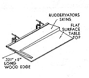
Now we're ready for the ruddervators. Later we will see that the flap and aileron sections can be placed on a flat surface during the drilling and gluing operations. But the ruddervators have a different thickness-to-width ratio at the root and tip ends. To deal with this, a jig can be made for the operation by nailing a wedge of wood .321" x 8" long to a flat-surface table and allowing the clamped bars at the trailing edges to overhang as shown in the drawing.
Here are the sixteen steps required for the construction of the ruddervators:
1. Adjust front bent angles of skins to fit ribs and form a gentle radius along trailing edge to form a smooth cusp when rear edges of skins are glued together. Pressing aft edge of skins against a 2"-diameter pipe will give desired results.
2. Install angle and counterbalance arm to tip rib and drive angle on root rib.
3. Clamp root and tip ribs in place on bottom skin and drill for 3/32" rivets.
4. Clean bottom skins and glue foam ribs in place.
5. When glue has set up, install metal ribs, drill, and dimple.
6. Clean ends of bottom skins and rib flanges, glue and rivet metal ribs to skins.
7. Place top skins on bottom skins and drill holes for 1/8" pop rivets through overlapping front angles. Omit holes in areas where hinges attach.
8. Clamp trailing edges between 21/2' x 3/4 " x 4' bars and check for 0-degree twist by taping straight strips of wood to centerlines of each end's rib and sighting them. Twist each ruddervator so that these sticks line up parallel when sighted from one end.
9. Drill second skin and rib rivet holes.
10. Remove clecos and bars and clean skins for gluing.
11. Apply glue, recleco, and reclamp bars at trailing edges. Check for 0-degree twist.
12. Install MK419BS pop rivets in overlapped front skin faces.
13. Drill 5-finger sections of hinge. Locate holes on centerline through each finger.
14. Tape hinge sections to elevators with 1/2 " wide masking tape between fingers. Shift hinges as necessary to get hinges to line up with sections on stabilizers.
15. Drill through hinge holes and ruddervator skins, remove chips, and attach hinges with MK42IBS pop rivets.
16. Cut, point, bend and install hinge pins.
That's it for the tail section, and now that the ice is broken, we'll assume that the reader is ready for bigger and better things. Next month's installment will be devoted to what it takes to build the HP-18's wing. See you then.
![]()
Because the facilities available to the grassroots homebuilder may differ from those used by Dick Schreder at Bryan Airport, SOARING has solicited inputs from enthusiasts who are building, or have built, an HP. From Scott AFB in Illinois, Tony Burton offers the following helpful hints for those tackling the HP's tail feathers.-Ed.

The tail should almost fall together; it's a fairly simple structure. But I realize for the virgin homebuilder it's the first part, and I well remember getting into a real sweat driving those first rivets. Here's something I learned the hard way-don't commit yourself too soon to the irreversible (like drilling a line of holes). Check everything three times first. Pilot drill when at all possible; don't enlarge to correct size until the last possible moment.
Another important principle: less can go wrong if you complete one thing at a time. For example, the instructions will have you drilling and aligning the hinges even before the skin is riveted to the spar, and assembling everything together. Logically there is nothing wrong with that, except for the perversity of inanimate objects, which will harass the beginner. A corollary of Murphy's Law must be, "A hole will not line up twice in a row." So, get the rear spar angle adjusted, rivet the skin on, recheck the straightness of the rear spar line, then it will be a whole lot easier to get three hinges positioned and attached. Do things slowly with at least as much thinking time as doing time, and the evils of getting ahead of thyself will be minimized.
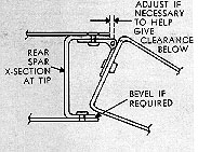
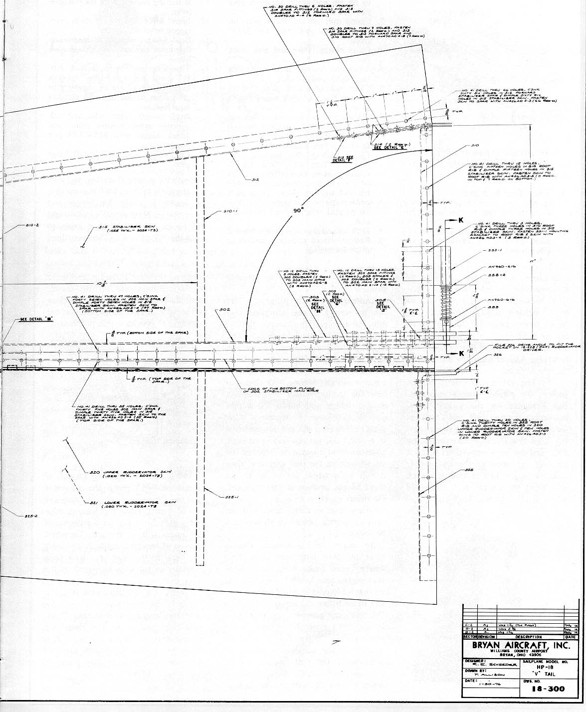
So much for principles. Details must be dealt with; here are three where I can make some suggestions that might prove helpful. Let's take the most troublesome one first-the necessity of adjusting the angle of bend on the rear spar progressively from root to tip, from about 84 degrees at the root to 90 at the tip. This is necessary because of the progressive change in position of the spar relative to the percentage-of-chord. Also, there is quite a tight fit between the rudder-vator and the spar at the tip, and there may be interference to full "up" travel, particularly if the tip hinge is too close to the spar. Beveling off the corner may help if you have this problem.
And it takes a surprising amount of muscle to bend down the stabilizer skin the "right amount." A four-foot 1" x 6" board along the leading edge and a little bouncing on it with hands and knees will do the job. The right amount of bend will result in a smooth line back to the rear spar with little tendency of the skin to lift off at the front spar.
Finally, the stabilizer skin is .032", which is the minimum thickness for countersinking a #40 drill bole. Countersinking just a bit too deep will feather-edge or enlarge the hole. It is better to err on the shallow side and have the rivet head slightly proud of the surface before it is set.