|
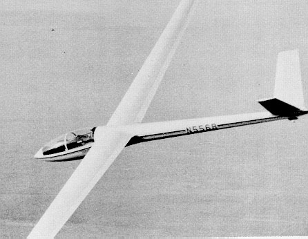
Full race-system in action. Photo shows full-span interlock of flaps and ailerons in high-speed cruise position. |
BUILDING THE HP-18
PART FOUR
By Richard Schreder
Soaring June 1976, Pages 35-39
This installment of the "Building the HP-18" series will detail the construction of the sailplane's flaps and ailerons. These surfaces are of great importance to the modern high-performance racing sailplane. With the establishment of the (unrestricted) 15Meter Class by the CIYY, the HP-18 is able to employ a full race-system wing that includes a flap range of 90 degrees to -10 degrees and an interconnect permitting the ailerons to droop or raise in concert through specified portions of their tip and down travel.
This system provides the following advantages: 1) it permits steep but slow-speed approaches to landing that are a great asset in cross-country flying (an added benefit is the greater visibility of steep approaches); 2) it i?iakes possible the achievement of low drag and high-speed cruise, particularly at low wing loadings (which can be a significant benefit after the premature dumping of water ballast); 3) thermal spiraling can be optimized at any weight (for a fuller exposition, see "Thermaling Turn Rate and Turn
Diameter" by Malcolm J. Abzug, SOARING, Jan. '74); 4) the interlocking of the ailerons further enhances the total effectiveness of the system, and, in addition, the span loading distribution is improved with a consequent reduction of induced drag.
|
Full race-system in action. Photo shows full-span interlock of flaps and ailerons in high-speed cruise position. |
Assembling flaps and ailerons:
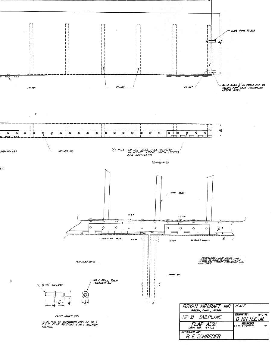
1. Flaps and ailerons are assembled from two pre-bent 4-ft. skins with a metal rib at each end and intermediate foam ribs spaced 4" apart. The flaps are driven from the root and are automatically engaged to control system when wings are mounted on fuselage. Each of the other three flap sections are driven by pins installed in the outer rib of the inboard sections. No rivets are used in end ribs or trailing edges as these joints are all glued with epoxy. One row of pop rivets is used in the front face of each section to hold the top and bottom skins together and to support the three hinge sections. The No. 4 flaps are 42 3/16" long and have one less foam rib than the other flap sections. The ailerons consist of two sections, one 48" long and the other 49" long. The control bell-crank is mounted on the inboard end of the inboard section and, like the flaps, the inboard section drives the outer section. Construction is similar to that of the flaps.
All flap and aileron sections have zero twist. It is very important that they be assembled on a table which is perfectly flat and free of twist.
Two aluminum bars 1/2" x 3/4" x 48" and eight 2-inch C-clamps will be required for clamping trailing edges together during the gluing operation. Three or four steel bars of similar size will be needed to lay on top of each section to hold the skin on the bottom rib contour while epoxy is curing. All metal tip ribs have been milled to exact size. The inboard driving ribs on the No. I flaps are formed from aluminum sheet. Foam material for all intermediate ribs is supplied in the form of precut strips of varying widths. The foam ribs for each flap section are cut from these strips with a razor blade or band saw.
2. Use the root rib for the No. I flap as a template and trace 22 blanks on the widest foam strips provided. Align the straight edge of the template along the straight edge of the strip. Nest the ribs together leaving just enough room between each tracing to allow for the saw cut. Saw or cut ribs apart. Accuracy is not essential. Leave all lines showing on blanks.
3. Make a wooden jig for each flap and aileron section. Place the root rib, 1 1 foam ribs, and the tip rib together on a 3/4 " board with the straight edge against the board and the forward edges aligned with the front edge of the board. Cut a wooden blank to the same shape as each metal rib from a 3/4" board. Place these wooden rib sections against the outside of the matching metal ribs and mark their positions on the board. Remove foam and metal ribs, drill two screw holes in each wooden rib and glue these ribs into position on the board. Replace metal ribs on jig with leading edges aligned with front edge of jig. Mark a line at the tip of each metal rib. Draw a line between these two marks and saw jig to this line. Remount all ribs and tighten screws in the end wood ribs against the metal ribs to clamp the assembly firmly together. Contact-cement a 1 1/2"-wide strip of emery cloth to one edge of 1 1/2" x 1 1/2" x 15" wooden block. Use this block to scrub down the foam ribs until the sanding block touches the metal ribs at each end. Finish off the front edge and trailing edge of the ribs in the same way. You will now have a perfect set of tapered ribs for the No. I flap section. The same jig can be used to make a set of ribs for the other No. I flap section. The slight difference in taper angle will be of no consequence. Make jigs and ribs for remaining flap and aileron sections in a similar manner. Remember that the No. 4 flap has only 10 foam ribs instead of 11.
4. Make sure that all ribs have the front lower corner sanded off to match the metal ribs, as this feature provides a vent opening the full length of each control section. This allows water drainage and pressure equalization throughout the structure.
5. A total weight saving of about 2 lbs. can be realized by drilling 1/2" and 3/8"-Iightening holes in the magnesium ribs. This is not essential but can be done by those who wish to reduce weight. Such holes should not come closer than 5/32" from any of the driving holes or outside edges of ribs.
|
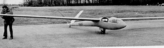
Ed Frappier completed his HP-18 this spring. He had an advantage not many '18 builders have -- he lives in Bryan, Ohio, Dick Schreder's hometown. Photo courtesy of Jim Wrinkle. |
6. Place No. 1 top skin upside down on flat, twist-free table. This is very important because any twist will be multiplied six times in the full length of one wing. Mark guidelines perpendicular to front of flap skin in 4" intervals starting from the outboard end. Use ballpoint pen. Use the root rib template to check the front bend angle of the skin. Increase or decrease as necessary throughout the full length to ensure perfect fit of all ribs.
7. Clean and scuff entire interior surface of skin and edges of the metal ribs.
8. Mark root end for trimming to 92 degree angle so that flap will fit against fuselage fairing properly. Take care not to touch cleaned skin surfaces or rib edges where glue will be applied.
9. Apply epoxy to top and front surface of all ribs and position them on appropriate skin lines with glued edge against skin. Place a straight bar on top of the ribs to ensure good contact with skin. Check each rib to verify that it is fully forward against the front flange. Make sure that the root rib is on the 92 degree angle line.
10. Pre-bend bottom skin to the approximate concave curvature required to fit the ribs. This can be accomplished by pushing the skin against a parallel tube about 3" in diameter. Four hands work better than two in this operation.
11. When top half has cured, the trailing edge cusp should be pre-bent into both upper and lower skins. This will prevent ribs from deforming skin when trailing edges are clamped together for gluing.
|
|
12. Put bottom skin in place on top of the assembly (flap is still upside down). Place a 4-ft. bar on the bottom skin aft of the leading edge to hold the skin against the ribs. Drill (No. 30) the first pop rivet hole through the skin lap on the front of the flap. Consult flap drawing 18-103 for proper location and alignment. Use the No. 30 drill guide attached with a cleco fastener to the first hole to drill the rest of the pop rivet holes. Omit holes in the areas where the three hinges will be attached. These holes will be put in later by drilling through predrilled holes in the hinges.
13. Remove clecos, file off any burrs around holes, and clean and scuff interior of bottom skin. Re-clean and scuff edges of metal ribs and skin trailing edge of assembled top half.
14. Apply epoxy to edges of all ribs and trailing edge of top assembly.
15. Place bottom skin on assembly, cleco leading edges, and clamp trailing edges between two 4-ft. aluminum bars. Bars should just overhang edge of table. Place heavier 4-ft. bars on assembly to hold bottom skin against ribs. Make sure both ends of flap assembly are firmly against the table surface and that bottom skin is touching the flap ribs. Pop-rivet the leading edge.
16. After No. 1 flap has cured, remove clamps and bars, trim off any epoxy from trailing edge or ends, and file root end so that it will lie in the same plane as that of the inboard end of the wing.
17. Hold flap section in place at the root end of the wing panel. Mark the ends of the wing hinges. Remove flap section and tape predrilled hinge sections to leading edge of flap with 1/2" masking tape between hinge fingers. A .065"-thick gauge should be used to ensure that hinge finger ends are .065" above extension of bottom surface. (This will position bottom flap surface in line with bottom wing surface.)
18. Hold flap in position on wing again to verify that hinges fit properly.
19. Remove flap and drill (No. 30) through predrilled hinge holes.
20. Remove hinges, clean chips, and pop rivet hinges in place.
21. File the outboard end of No. 1 flap section so that it is square with the hinge line.
22. All other flap and aileron sections are made in the same way except that all inboard ends are square with the hinge axis. No. 4 flap is approximately 42" long but do not trim until inboard aileron is mounted. The skin blanks are 42 3/16" long but the outboard magnesium rib should be set inward on the 41 3/4" mark. After the No. 4 flap sections have been mounted, the space from the end rib to the end of the skin can be filled with foam epoxied into the recess. The outboard aileron section is 49" long. The inboard end of the inboard aileron has a small bell-crank riveted to the magnesium rib.
23. Driving pins must be installed in the outboard ends of flap sections 1, 2, 3, and inboard aileron. These pins are installed by pressing a washer to the midpoint and then epoxying them in place in the two holes provided in each magnesium rib.
24. Each flap section should be squared off at both ends and positioned on the wing so that there is a 1/8" gap between it and the next inboard flap section when the hinges are attached. The outboard end of the No. 4 flap should not be trimmed to length until the inboard aileron has been mounted. After this section has been installed, the outboard end of the No. 4 flap can be trimmed so that it has 1/32" clearance between it and the aileron. A 1/16" gap between the two aileron sections should be allowed. The outboard end of the outboard aileron section should be trimmed to provide a 1/32" gap between it and the wing tip plate (skid).
25. At least one rivet should be placed in each trailing edge corner to deter separation of trailing edges if flap and aileron sections are bumped or damaged.
26. Trim trailing edge of top wing skin as per drawing. Skin should remain in contact with flaps until they exceed 10 degrees down. Trim line should match top leading edge of flaps when they leave upper skin surface. Top skin in aileron portion of wing should be trimmed forward to the edge of the spar. Aileron gap covers should be epoxied on top of skin in this area.
Finishing wing surfaces:
1 . File off the heads of any 426 rivets that extend more than approximately .005" above the wing surface. Micrometer rivet head planishers are available for this purpose.
2. Scrub entire Surface with Scotchbrite pads and Metal Prep etching solution. Rinse with clean water. Surface is clean when water will lie flat for 60 seconds without contracting. Rescrub if necessary.
3. Wipe dry with clean cloths or paper towels to remove mineral deposits.
4. Spray with thin coat of zinc chromate or other suitable aluminum primer.
5. Spray with white lacquer primer surfacer.
6. Fill heads of pop rivets with primer surfacer putty.
7. Low spots can be filled by applying a teaspoon or less of unthinned lacquer primer surfacer to the area and spreading it with a screed. The screed is a piece of .032" stainless steel 3" x 12" perfectly straight edges and slightly rounded corners. Make three or four passes with each application. Each pass deposits an additional thin layer until all primer is distributed. Any free primer remaining after the fourth pass should be removed by continuing the last pass beyond the leading edge. A quick flip of the stainless steel screed will prevent the remaining lacquer from dripping off onto the floor. This residue is unfit for further screeding because it has become too thick and contains gritty particles. Scrape it into a can to be salvaged for spraying surfaces later.
8. Succeeding passes can be made in either a chord-wise or span-wise direction as developing surface indicates.
9. Keep applications thin to allow rapid drying.
10. When necessary to remove ridges, sand with 180-grit dry paper.
11. Finish by sanding with 400-grit dry paper. No further finish is required for aerodynamic smoothness and wings can be left in this sanded finish condition as they are easy to maintain and retouch. Bugs and dirt can be sanded off with 400-grit wet or dry sandpaper. If a glossy or a more permanent finish is desired, lacquer or acrylic enamel can be applied. Dark colors should not be used as they result in heating of the wing surface when exposed to bright summer sun. This is hard on the finish, thickens the boundary layer, which will cause more drag, and raises the interior wing temperatures which could seriously weaken the ribs or adhesive.
Next month: Building the Fuselage
|
Blue Prints (about 60k each.) |
|
FROM THE BUILDERS
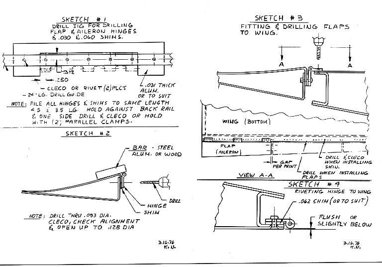
Fitting flaps and ailerons is an exacting process. Konrad Nierich once again has some helpful suggestions: "Here is a variation to Dick's approach on fitting these surfaces. A small drill jig made from the 24-inch drill guide (see sketch #I) was used to predrill all hinges and shims. Then the flaps, where completed, and hinges and spacers pop riveted in place (see sketch # 2). Leave out lower rear spar holes where flap or aileron hinges fit (see sketch #3). With skin clecoed to wing, bottom side up, position flaps on top of rear spar and drill through predrilled hinges into rear spar. Cleco as you go. Space the next flap with drive pins engaged and proceed with drilling and cleco. A shim .026 inches thick will be needed under the hinge to get proper alignment (see sketch #4). Rivet hinges and shims when gluing lower wing skins. Hinges and shims can be bonded to rear spar prior to gluing skins; it will reduce confusion during bonding of wing skins!
"The predrilled rear spar sections must be carefully checked to match the height of the rear ribs and flaps. Re-drill, if necessary!"
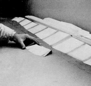 Even though plastic foam ribs are placed only four inches apart compared to eight inches for metal ribs, their weight is still only half as much.
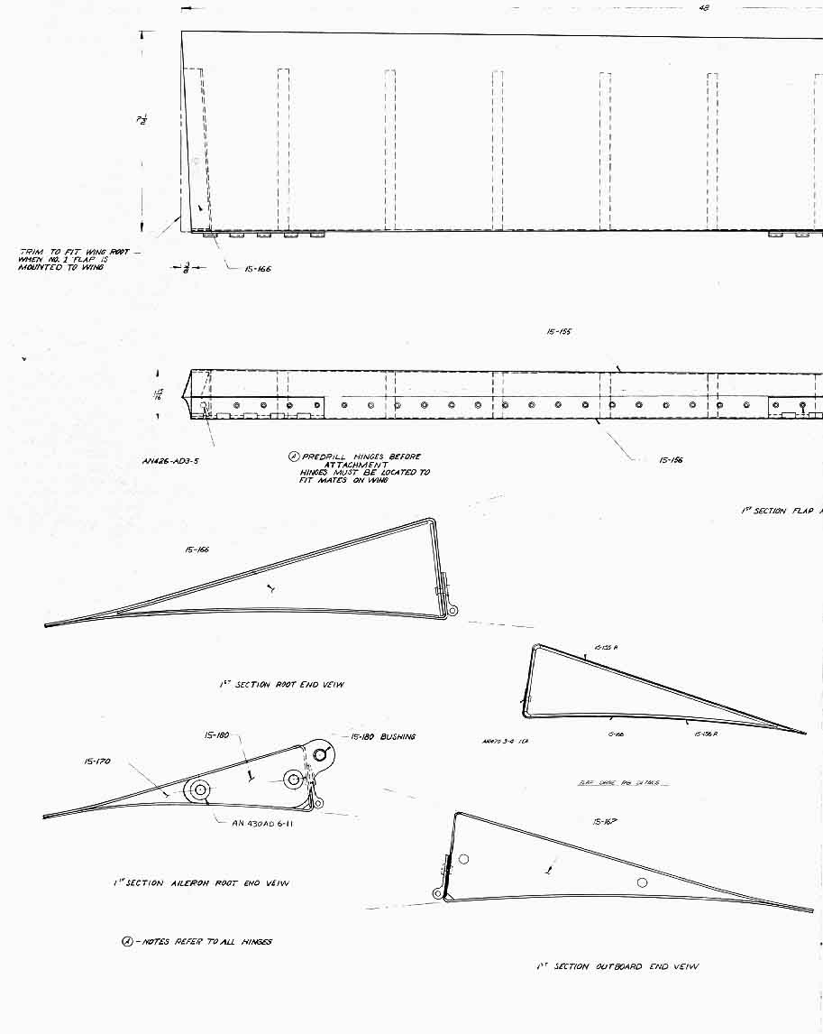