Building the HP-18
PART SIX
by RICHARD E. SCHREDER
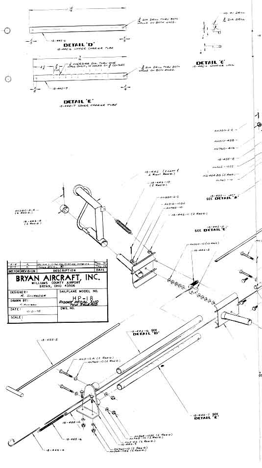
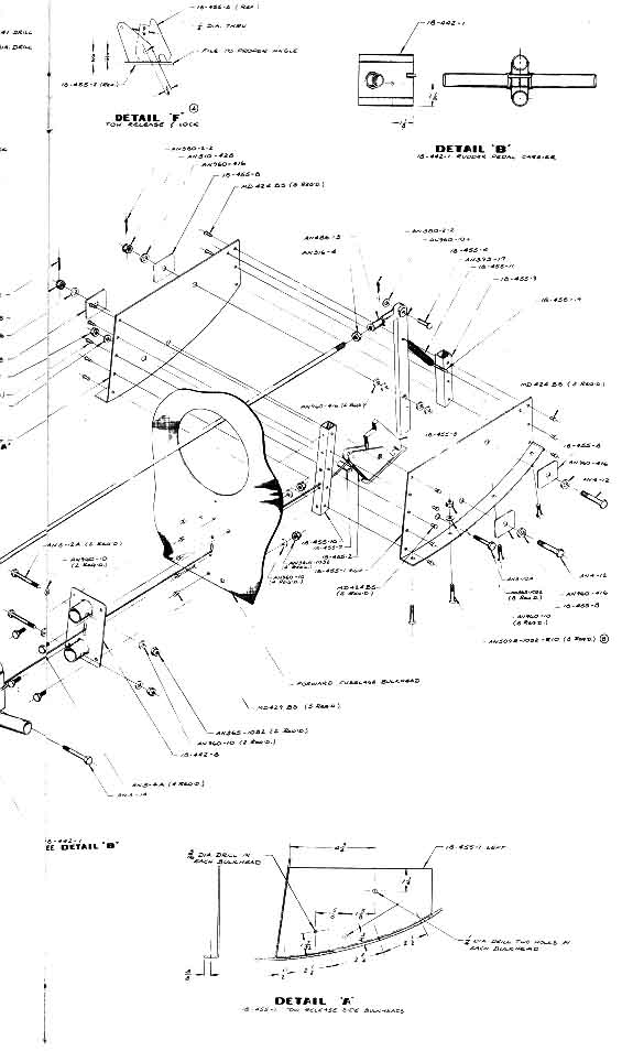
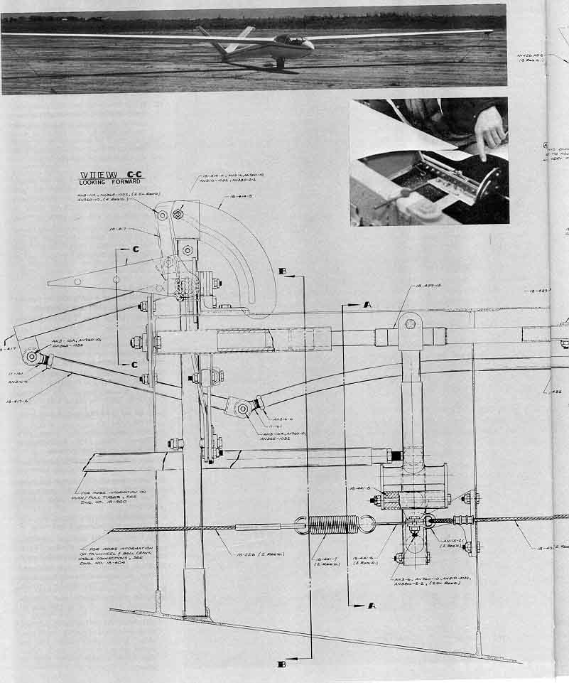
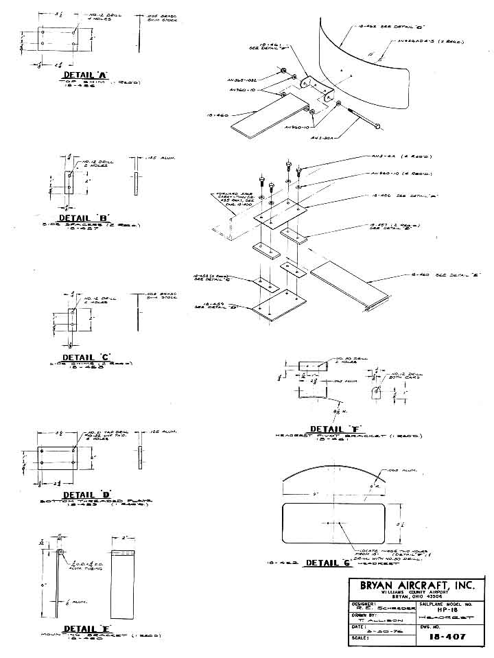
With this issue, "Building the HP18" has reached the sixth installment -the completion point announced when the series was begun in the March SOARING. Originally, Dick Schreder planned that the final article would be devoted to the construction of the '18's trailer. However, it has proved impractical to publish the complete directions and drawings in the available space, and so the present article deals with wrap-up tasks of detailing, assembly, weight & balance, etc., as well as drawings for the headrest, tow release and rudder pedals, ruddervator mixer, and tail wheel assembly that couldn't be included last month. In the meantime, the Society asked Dick to pinch-hit as U.S. Team Captain at the World Gliding Championships in Finland when Jim Herman had to bow out just before the contest. As a result, the trailer installment will be postponed until a later issue.
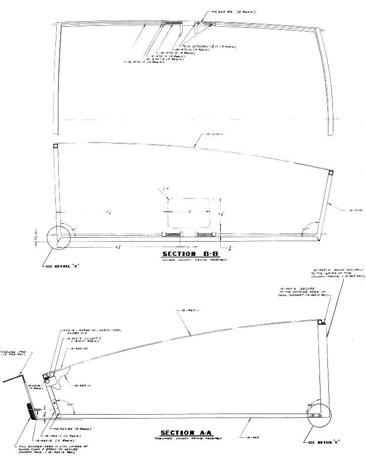
Assembling the Canopies
1 . Install the attach pins and clip assemblies to the frames. Allow .100inch setback on each side of the fuselage for the thickness of the canopy glass. Shims can be placed under the frames and clips to raise canopies if necessary.
2. Place windshield canopy over mounted frame and mark preliminary trim lines with masking tape.
3. Saw canopy to edge of masking tape with fine-toothed band saw.
4. Sand and fit canopy edges until glass sets in place perfectly.
5. Mark edges of windshield glass leaving 1/2 " setback uncovered around inside edges.
6. Clean frame with MEK or lacquer thinner and roughen with Scotchbrite on the two exposed sides.
7. Spray exposed surfaces of frames with flat black lacquer.
8. Apply three coats of Roberts Contact Adhesive to frame and masked canopy glass.
9. Reinstall canopy frame and mount glass while cement is still slightly tacky.
10. Remove windshield and fill any open spaces between glass and frame with more adhesive and allow to cure.
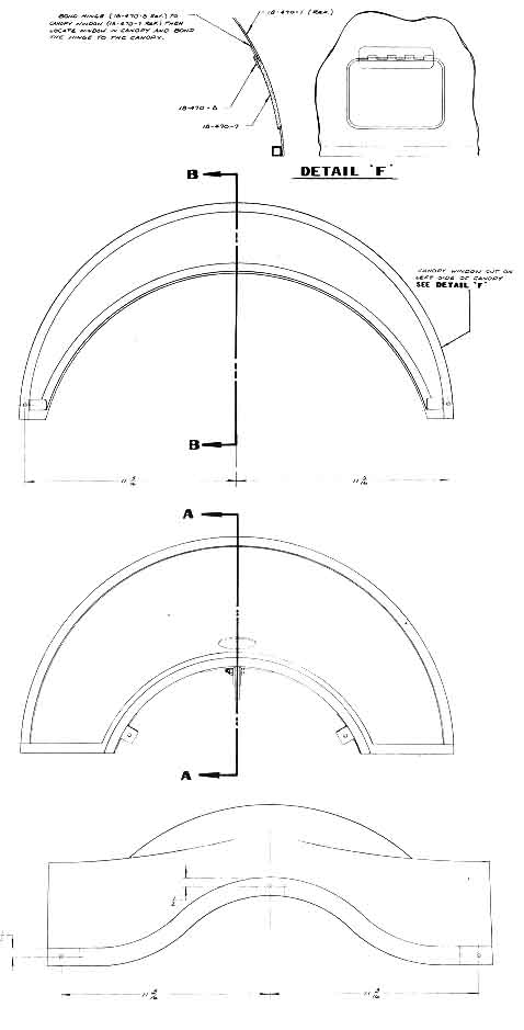
11. Repeat steps 2 through 9 for the center canopy.
12. Check fit of canopies and if O.K., install clips on fuselage side rails to hold canopies in place.
13. Carefully mark attach pin hole locations in wing cover and front fuselage coamings. Drill holes (No. 12).
14. Apply 1" white vinyl tape on outside of glass over canopy frame. Wrap excess 1/2" overhang around edge of glass onto bottom front and rear of frames.
15. Cut hole in side of center canopy by scribing around cutout pattern and drilling a series of adjacent No. 30 holes. Stone cutting edges of drill flutes before using to prevent chipping.
16. File opening, fit and mount canopy window.
17. Install front canopy vent using same procedure outlined in 15 and 16 above.
Mounting tail and fairing to fuselage:
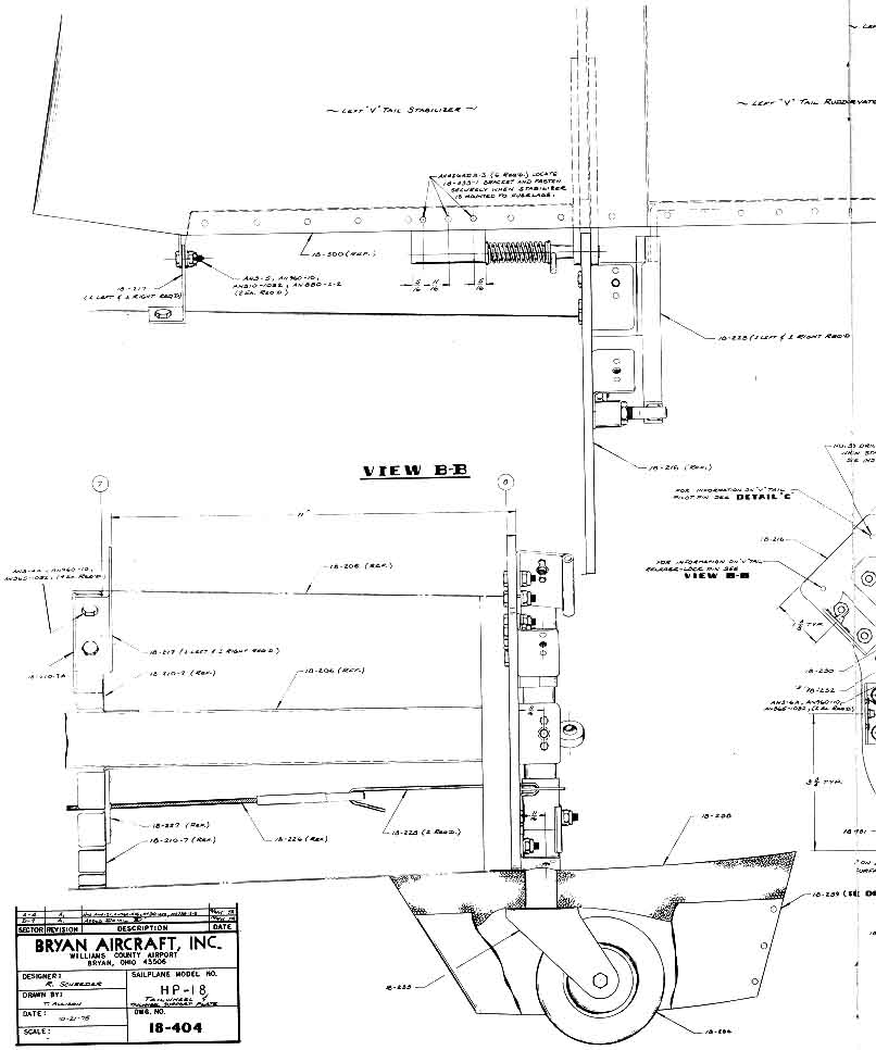
1. Install stabilizers on rear stabilizer spar carry-through plate which has already been bolted on rear fuselage bulkhead.
2. Clamp rear spar fittings together on plate with four C-clamps.
3. Align stabilizers so that No. 30 pilot holes in rear spar fittings align with centers for corresponding holes in tail carry-through plate.
4. Check included angle between rear spar centerlines to equal 90 degrees.
5. Place bar across tips of stabilizers and another bar across the fuselage on the main wing spar centerline.
6. Sight tail bar into front bar and shift stabilizers as necessary to get both bars to sight parallel. Both bars must be perpendicular to fuselage centerline.
7. Brace stabilizers so that they can't shift. Clamp front spar fittings to fuselage fittings.
8. Run No. 30 drill through fittings and tail plate and install long 1/8" rivets or 1/8" pins. Make sure holes are centered okay in tail plate.
9. Recheck alignment of bars and drill with number 12 drill.
10. Install 10-32 bolts and nuts.
11. Recheck alignment and drill with 1/4" drill.
12. Install 1/4" bolts and nuts.
13. Recheck alignment and drill two top holes with 5/16" drill.
14. Recheck alignment and ream holes with a No. 3 B & S reamer from rear to front. Ream only enough to allow tapered pin shank to stop 1/32" short of coming through the forward edge of the stabilizer fitting. If the hole is reamed too large, washers will have to be used to draw nuts up tight. Be sure reamer is perpendicular to fittings.
15. When top holes have been reamed and tapered pins are installed and bolted tight, remove rear plate and stabilizer assembly from fuselage and rest it on the floor with leading edges up from front to rear.
16. Remove 2 lower bolts, drill to 5/16", and ream lower holes with reamer installed in a long extension tube so that lower tapered pins will just go through spar fittings with 1/32" of pin tip extending beyond the rear surface of rear fitting.
17. Drill No. 30 holes through front spar fittings.
18. Reinstall stabilizer and rear carrythrough plate assembly with all 4 tapered pins in place.
19. Support the front spars in position on the fuselage, attach fittings and measure hole distances from the fuselage. They should be the same distance from the fuselage skin and fuselage top centerline if the stabilizers are both alike.
20. Drill (No. 30) through the front spar and matching fuselage fittings on both stabilizers.
21. Install two 1/8" rivets and fold tail surfaces upward until the tips meet. Top tapered pins should be loosened enough to prevent scoring top rear fittings when folding. Tips should be aligned equally fore and aft when they come together. If they don't, holes in the stabilizer front spar fuselage fitting will have to be drifted with a small round file to get proper folded alignment.
22. Drill out both fitting holes with a No. 12 drill and install 10-32 bolts.
23. Recheck vertical folding alignment.
24. Remove 10-32 bolts and redrill holes to 1/4 ".
25. Install 1/4" bolts.
26. Install lower tapered pin supports, drill and install rivets in root rib flanges.
27. Cut upper stabilizer fairing as necessary to let spar fittings clear fairings when tail surfaces are folded.
28. Cut slots in lower stabilizer fairing to clear taper pin actuating pin when it moves forward to unlock stabilizers for folding.
29. Trim top stabilizer fairing to fit and allow folding of both sections without catching on edges.
30. Install stabilizer ribs in fairing to match fairing shape to stabilizer root sections.
31. Install elevators and hinge pins.
32. Fit tail fairing to fuselage so that fairing edges clear elevators by 1/8".
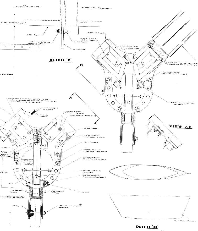
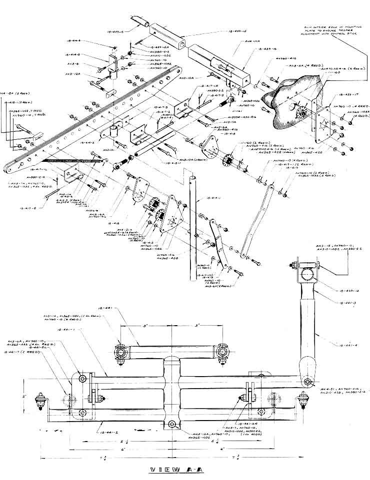
33. Install ruddervator drivers as per drawing.
34. Drill screw attach holes (No. 12).
35. Bolt push-pull tubes to ruddervator drivers.
36. Make cut-outs in tail cone to clear ruddervator drivers when tail surfaces are moved 30 degrees up and 25 degrees down.
37. Attach cables to tail wheel yoke.
38. Install tail wheel and tail wheel fairings.
Mounting the wing panels:
1. Trim out the vertical wall on the right and left lower wing fairing from the leading edge to the bulkhead just aft of the rear spar position. The fairings should be left at the original thickness except in the area under the main spar. In this area, the thickness should be reduced to no less than 3/32". Cutting the fairing any thinner will weaken it and result in damage during assembly and disassembly of the sailplane.
2. Hold the root rib airfoil template against the side of the wing fairing with the centerline of the front spar fitting 1/8" behind the front face of the seat back and mark the centerline position of the main spar on right and left sides. Front spar carrythrough angle, forward face, should be even with the top of the seat back bulkhead.
3. Draw a fore and aft centerline for the fuselage on the horizontal bulkhead in the area where the main spars will join.
4. Measure from this centerline out to the right and left edges of the bottom fairing. These edges must be trimmed to allow a minimum 1/16" gap between fairing and wing skin when wings are joined on the fuselage. Wings may be joined at the main spar and lowered onto the fuselage which must be properly braced to support the extra weight.
5. Stretch a string from wingtip to wingtip and move tips of wings fore or aft as necessary to keep the string directly above the center of the spar at the main fittings. The fuselage must be level. This is accomplished by supporting the tail cone so that its side centerlines are perfectly level.
6. Using a 50-foot tape or length of wire, shift wings so that the distance from the center of the spar at each tip to the rear centerline of the tail cone are equal.
7. Trace along wing-root skin onto fairing to establish trim line.
8. Cut, fit, and assemble the front and rear spar carry-through and the main wing spar angles. The front and rear spar carry-through assemblies must be trimmed to fit the upper surface of the bottom wing fairing.
9. Remove the wings and trim the fairings. Maintain an approximate gap of 1/16" between the outer edges of the fairings and the inboard edges of the wing skins at the root ribs.
10. Replace wings on fuselage.
11. Check once more to make sure that everything lines up properly and drill holes through the angles into the horizontal bulkhead.
12. Make sure that the front, center, and rear bulkhead carry-through angles rest on a single plane with no twist when viewed from the front.
13. Check to make sure that wing panels are aligned properly with the fairings on each side so that the fairing extends a uniform distance of about 1/ 16" below the wing skin. A further check would be to install identical top root-rib templates on each root rib and sight the tops to be parallel. This is your last chance to make any further adjustments before the wings are finally mounted. It is important that one wing panel does not have more incidence than, the other.
14. Pilot holes can now be drilled (No. 12) through proper centers on the front and rear spar carry-through fittings. Before drilling, make sure that the resulting holes in the front and rear wing drag fittings will have sufficient edge distance for the 3/8" drag pins. This distance should be a minimum of 7/16" radius. Drill drag fitting holes in successive steps with several sizes of drills and finish up with 3/8" hand reamer. If long drills are not available, extensions can be made by boring a length of 1/2" rod with appropriate, snug-fitting holes for each drill.
15. After 3/8"drag pins have been installed, the mounting holes through the main spar retaining angles can be drilled. Remove the front main spar angles and drill through main spar bushings and the rear angle.
16. When you are satisfied that everything is lined up properly, you may mark and drill the holes for the bolts which hold the angles to the horizontal fuselage bulkhead.
17. Remove the rear angle, reinstall the front angle, and repeat the same process.
18. This finishes the mounting of the wing except for fitting the fuselage wing cover. Once again, the portion of the cover that rests on the main spar must be sanded to about 3/32" thickness.
19. Trim side edges of the main wing cover so that it will fit between the wing skins on each side. It is important that the root end of the wing skins are filed straight and are ready for this operation.
20. Trim the aft edge and leading edge portions so that the cover will give the best fit possible around the leading edges and where it joins the main pod at the rear end of the cover.
21. If all has gone well to this point, there will be a good fit all the way around each wing juncture. If one leading edge fits and the other does not, it may be necessary to add some fiberglass inside or outside the leading edge radius and file to fit.
22. Consult the wing covering drawing for location and size of the proper reinforcements to support the pins for attaching the cover to the fuselage. Install stiffeners in cover in accordance with this same drawing.
23. Install mounting pins in cover bosses and match them with holes in forward attaching angle brackets and in fuselage bulkhead at rear end of cover.
Painting the HP-18
1. Wash all metal surfaces to be painted with clean water and detergent.
2. Scrub entire area with Scotchbrite pads soaked with Dupont No. 5717 metal conditioner. Be sure to scrub every square inch as proper surface preparation is essential to obtain adequate adhesion.
3. Rinse surfaces cleaned with fresh water. If water will not lie flat for sixty seconds, repeat the cleaning process until the water will lie flat.
4. Wipe surfaces dry with cleanly laundered soft rags.
5. When completely dry, spray with Dupont No. 1008 multi-purpose lacquer-type primer surfacer.
6. Fill pop rivet holes with primer surfacer.
7. Use a piece of .025" x 3" x 12' stainless steel to screed primer over rivet rows, depressions and' other irregularities.
8. Sand entire surface when dry with 180 and 400 finishing paper.
9. If large irregular surfaces exist they can be sprayed with Feather-Fill. It has good adhesion and sands freely.
10. When surface is dry, smooth, and free of any surface defects, sand with No. 400 dry finishing paper.
11. Spray entire surface with Dupont Centuri 817A white acrylic enamel or white acrylic lacquer. White is recommended for the entire sailplane because it stays cooler in bright sunshine. Dark colors could cause internal temperatures to reach values that might damage plastic foam or epoxy.
12. Gloss may be removed with No. 400 wet finishing paper when enamel is dry.
13. The fuselage should be painted the same as the wings and the tail. Maintaining a gel coat finish entails entirely too much labor and wings and fuselage will be perfectly matched in color if painted. All fiberglass parts should be sanded with 400 grit paper before being painted.
14. "Experimental" lettering can be placed on each side of the cockpit by using 2" high adhesive backed printed letters.
15. Decorative striping can be added to the fuselage sides with 1/2" and 1", wide colored vinyl plastic tape. One inch red and 1/2" blue spaced 1/4" apart makes a pleasing contrast.
Determining the gross weight, the center of gravity (cg), and verifying that they are within proper limits is very important.
If the cg is too far forward (less than 25% MAC), the ship must be flown continuously with up elevator and control may be insufficient for normal flare-out and landing.
If the cg is too far aft (more than 40% MAC), longitudinal control will be unstable and recovery from spins may be impossible.
Flying overweight or overspeed reduces strength safety margins and can result in structural damage or catastrophic failure.
The weight and balance should always be calculated with and without water ballast if water is to be carried since the water is normally dumped before landing. The main spar tank is centered on the 41.25% MAC and will tend to move the center of gravity aft when water is carried. A lightweight pilot who could fly without ballast and stay within the 40% MAC limit could be too tail heavy when water was added. Conversely, a heavy pilot just within the 25% MAC when carrying water ballast would be too nose heavy after dumping the water.
Gross weight should not exceed 750 lbs. without water ballast unless the builder is willing to accept lower allowable load factors and obtains FAA approval for such weight increases on his operating limitations.
Let's get started on the weighing and measuring:
1. Use two bathroom scales to weigh the sailplane. The main wheel should be placed on a 3/4" plywood board about 9" x 24" that rests on two scales. A wooden wedge cut from a 4" x 4" x 18" block of wood with one end equal to the height of the top of the plywood board makes a good ramp to roll the ship up onto the scales.
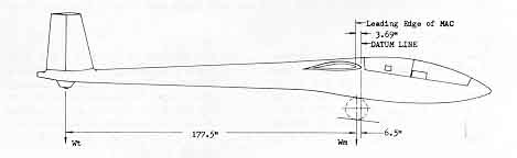
2. The tail wheel should be set on a box of such height that the tail cone centerline is level. Measure the horizontal projection distances between wheel centers. Establish a line on the floor by connecting two points found by dropping a plumb bob from the leading edge of each wing at the sides of the fuselage. The distance between this line and a parallel line passing under the center of the main wheel gives the distance from the main wheel to datum. This distance will vary if the shock struts are not fully extended, so make certain that there is enough air pressure in the shock system to tighten the restraining cable.
3. Scales should be adjusted to read zero before the ship is placed on them. After weighing, the scales should be calibrated for correction error by checking their reading against that of a platform scale weighing an object of approximately the same amount as the part of the ship each scale was supporting. Apply these corrections and deduct the weight of any blocks or boards added after the scales were zeroed. Add the two net readings for Wm (main wheel weight).
4. Roll the ship off the scales and relevel the fuselage with the tail wheel resting on a scale properly supported to level the rear fuselage centerline. Read the scale with and without the pilot in the cockpit. Record the net weights.
A. Weight and balance calculations for the HP-18, Serial No 1, N5568, 2/29/76. Equipment included: instruments, radio, battery, speaker, microphone 16-lb. parachute.
|
Wm Weight on main wheel |
Wt Weight on tail wheel |
W Total weight |
|
Empty --- 450 lbs. |
52 lbs. |
502 lbs |
|
W/212-lb pilot --- 712 lbs |
12 lbs. |
723 lbs. |
B. Determination of pilot cg location by moment differences in tail wheel scale readings with and without 221 lb. pilot in ship
52 - 12 = 40 lbs.
221P = 40 X 177.5"
P = 32.13" = cg distance of pilot from main wheel
32.13" - 6.5" = 25.63" = Pilot weight moment arm forward of datum
C. Determination of empty cg of N5568
Sum of moments about datum
(6.5" + 177.5") X Wt + 6.5" X Wm = W X L
L = (184 Wt + 6.5 Wm)/(W Total)
L = ((184" X 52) + (6.5" X 450))/(502)
L = (9568 + 2925)/502 = 24.89" aft of datum @ 502 lbs.
D. Determination of location of cg range
MAC = (113 X 144)/590.55 = 27.55"
Root Chord = 36.5"
E. Determination of maximum and minimum pilot weight without ballast
Max. pilot weight, cg at 25% MAC (10.58")
W max X (25.63 + 10.58) = 502 X (24.89 - 10.58)
W max X 36.21 = 502 X 14.31
W max = 198.3 lbs.
Min. pilot weight, cg at 40% MAC ( 1 4.7 1
W min X (25.63 + 14.7 1 ) = 502 X (24.89 - 14.7 1
W min X 40.34 = 502 X 10. 1 8
W min = 126.7 lbs.
F. Determination of maximum and minimum pilot weight with 200 lbs. of water ballast
Maximum pilot weight, cg at 25% MAC (10.58")
W max X (25.63 + 10.58) = 502 X (24.89 - 10.58) + 200 X (15.05 - 10.58)
W max X 36.21 = 7184 + 894
W max = 223.09 lbs.
Minimum pilot weight, cg at 40% MAC (14.7 1
W min X (25.63 + 14.71) = 502 X (24.89 - 14.71) + (200 X (15.05 - 14.7 1))
W min X 40.34 = (502 X 10.18) + (200 X .34)
W min = 128.37 lbs.
G. NOTE: As pointed out above, the maximum pilot weight of 223.1 lbs. with water ballast can't be used without tail ballast because dumping water reduces the maximum allowable pilot weight to 198.3 lbs. Likewise, the 126.7 lb. minimum pilot weight for an unballasted ship would be 1.7 lbs. under the minimum pilot weight if full water ballast is added.
H. A general rule for adding tail ballast for an overweight pilot is to multiply his excess weight by the ratio of his distance from the 25% cg divided by the distance of the ballast from the cg. (Ballast located in the stabilizer fairing.)
I. Example 1: How much ballast (Wbal) would be required for a 250 lb. pilot?
Wbal (250 - 198.3) X (25.63 + 10.58)/(176 - 10.58)
Wbal 51.7 X .219 = 11.32 lbs. in the tail
J. Example 2: How much ballast would be required for a 100-lb. pilot with 200 lbs. of water ballast?
Wbal = (126.7 - 100) X (25.63 + 14.71)/73
Wbal - 26.7 X .55 = 14.75 lbs. in the nose
K. It is recommended that small pilots use a cushion behind their backs to keep their body cg's farther forward at the normal 25.63" position. This will also help shortlegged pilots to reach the rudder pedals when the full aft pedal adjustment is insufficient.
L. Optimum cg location for competition flying is 40% MAC as tail balancing loads will be near zero in this condition and tail drag will be at a minimum. Stability is near neutral and elevator control loads are very light with this loading condition.
Flight Testing
1. Calculate your cg location and placard your ship for maximum and minimum pilot weight to stay within permissible cg limits. The allowable cg travel is from 25% to 40% MAC or 10.58" to 14.71" aft of the datum which is the leading edge of the wing root.
2. If your loaded cg falls outside this range, carry sufficient ballast to bring it within limits.
3. Check the entire control system and attaching pins or bolts for cotter keys and all nuts and locknuts for tightness to insure that nothing can come apart or change setting.
4. Set control surfaces in neutral positions and ascertain that stick and rudder pedals are in neutral.
5. Move all controls, check for proper direction, extent and freedom of movement.
Elevators: Up - 15 degrees, Down - 10 degrees
Rudder: Right - 15 degrees, Left - 15 degrees
Ailerons: Up - 20 degrees, Down - 15 degrees
6. Operate flap to make certain that it works freely and does not bind when retracted. Ailerons should move with flaps from -10' to +10'. Be certain that aileron stick movement is not restricted by full movement of flaps.
7. Check tow release for proper action.
8. Make sure canopy pins open and close freely.
9. Test-flying a newly-built sailplane is not a proper undertaking for a pilot with no experience in a sailplane, so don't waste a lot of hard work by trying to fly your ship if you don't have at least a private pilot license with a glider rating.
10. For the first flight, select a long sod field or aide runway free of closely set lights that could catch a wingtip. Most important, take off directly into the wind.
11. The flight should be an airtow of only a few feet in height with release made in plenty of time to land straight ahead without danger of running out of field. With flap settings of 30' or less the ship will float excessively so be ready to crank in more flap if necessary to stop.
12. The purpose of the first flight is to check control reactions and general flight "feel" without getting dangerously high. Flaps can be set at 30' for this flight and left at this setting unless it is necessary to land quickly. Then, of course, full deflection should be used.
13. The characteristics of flaps are considerably different than those of spoilers and different flight techniques are required. Below are points to remember:
A. Flaps increase lift, spoilers decrease lift. Hence, to maintain a constant altitude above the runway, the nose must be lowered with flaps and raised with spoilers.
B. Flaps decrease landing speed, spoilers increase landing speed.
C. Always start takeoff run with flaps in full up position if ailerons are interconnected. This practice will greatly increase aileron effectiveness at low speed.
D. Small flap deflections will increase the "floating" tendency and may extend the distance covered before touchdown.
E. Large flap deflections increase drag tremendously and make steep angles of approach necessary to maintain flying speed.
F. Flap deflections increase the effective angle of attack of the wing and result in a stall at lower fuselage angle of attack.
G. Complete stall with full flap is approximately the same attitude as the "at rest" position on the ground.
H. When cranking in more flap close to the ground during landing, it will be necessary to push the stick forward to avoid "ballooning" due to the additional lift.
I. Always approach for landing at 60 mph. Maintain this speed while cranking flaps up or down to adjust your approach angle.
J. You can safely retract flaps at 60 mph to extend your flight if you get too low.
K. Never come in low and slow with large flap settings since you can do nothing to extend your glide if you get too low.
L. Full flap deflections provide extremely high drag and steep approaches and, unlike most spoilers, they are very effective at low speeds.
M. If the ship is floating down the runway and doesn't want to slow down, you just don't have enough flap cranked down.
14. After landing, always hold stick back during landing roll to keep tail wheel on ground for positive directional control. Pushing the stick forward can result in a ground loop especially in high grass.
15. After the first low altitude flight has been made and all reactions are normal, you are ready for a full airtow.
16. Have the tow pilot briefed to maintain 60 to 65 mph. Use a towplane with sufficient power to climb decently and use an airfield sufficiently long so that you can get back safely in case of a premature release. 3000 feet is considered a minimum height for an initial test-flight airtow.
17. After release, practice using the flaps to familiarize yourself with their action.
18. Flight characteristics of the HP-18 are normal. No unusual habits have been noted. Control forces are lighter than most sailplanes with small deflections required for circling and most maneuvers. Stalls with a 200-lb. pilot are very gentle from both straight and circling flight. The ship will spin if it is kicked in with rudder while the stick is held back. Recovery is positive but at a slower rate than a Schweizer 1-23 or 1-26.
19. Most sailplane accidents occur during landings. It seems very foolish to destroy your sailplane and injure or kill yourself just because you don't bother to observe a few basic safety measures before you land. Here theyare:
A. Always keep track of the wind direction.
B. Never fly over terrain with no safe landing area in view.
C. Pick the largest field lined up with the wind with the lowest grass, weeds, or crops.
D. Give up thermaling or lift-hunting while you are still high enough to reach your field. Fly a 360-degree pattern and spot all possible hazards.
E. Don't make long straight-in approaches; they can end with an overstretched glide, stall, and disaster.
F. Don't land on highways.
G. Keep a sharp lookout for other aircraft, wires, stakes, ditches, holes, fences, terraces, pipes, rocks, and other possible landing hazards.
|
Blue Prints |
|||