WINGLET DESIGN FOR SAILPLANES
by
Peter Masak
INTRODUCTION
In the ongoing quest for higher performance sailplanes, winglets have provided a means for improving the performance with only a modest price per L/D point gain. Winglets act to reduce induced drag and act to control the cross flow in the tip region of the wings in such a way as to improve the handling characteristics at the same time.
By introducing a vertical cambered surface at the tip, the downwash field behind the wing is spread horizontally by several inches. Since the induced drag is inversely proportional to the effective width of this downwash field, the winglet therefore acts to reduce induced drag by displacing the vortices outward. Presumably the greatest effect would be obtained by introducing a high lift large surface winglet which would displace more air outward and alter the circulation pattern in a more significant way. However, the design of winglets involves the compromise of maximizing the low speed improvement without sacrificing high-speed performance. Pilots will not fly with winglets if they perceive any deterioration of high-speed performance.
BACKGROUND
First Use of Winglets
Winglets for modern aircraft were first proposed by Dr. Richard Whitcomb
at NASA Langley in the mid-1970's. At that time, wind tunnel models and subsequent
full size flight tests on a Boeing 707 commercial jetliner demonstrated a
significant reduction in total drag at high lift coefficients.
After the publication of the design philosophy, numerous researchers in industry tackled winglet design with varying degrees of success. Most tried to use potential flow methods for predicting tip inflow angles and surface pressure distributions, however given the nature of the flow field at the tip, this has lead many investigators to the wrong conclusions.
Potential flow analysis seems to steer to designer in the direction of excessively large winglets, while experimental data suggests that large winglets pay a greater-than-predicted penalty in high speed performance. Since potential flow methods cannot accurately predict the vortex roll-up at the tip, or the influence of secondary flows on the boundary layer, these methods have not provided the complete picture of the effect of the winglets on performance. Also the potential flow methods do not show the significant influence of the fore and aft positioning effect of the winglets.
Experience with Sailplanes
In sailplane racing circles, winglets were tried and then dropped by a number
of University Flying Groups (Darmstadt, Braunschweig), and the French manufacturer
Centrair. The overriding concern repeatedly expressed by racing pilots was
that the winglets, although they were known to provide a significant gain
at low speed, would detract from performance at the high speed cruise condition,
with a resulting net loss or perhaps no achieved gain in overall performance.
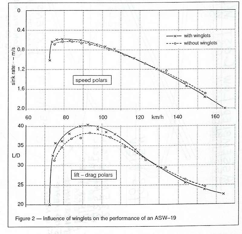
This concern is justified since winglets act to reduce both induced drag and drag due to crossflow at the tip: however, at high speed neither of these effects are large and thus there is some speed at which the overall surface friction drag of the winglet exceeds the induced interference drag reduction provided by the winglet. The graphs in figure 2 shows this effect with large winglets added to an ASW-19 at Braunschweig. Clearly the key is to provide a minimum drag surface which does not stall at circling speeds.
Prompted by interest from Dr. David Marsden at the University of Alberta, and my own successful experience a decade ago with a home-built HP-18, the challenge was struck to design an efficient pair of winglets for a Nimbus III for the World championships in 1989 at Wiener Neustadt, Austria.
Marsden had proposed using an unusual double element winglet on the Nimbus III (emulating the primary wing feathers of a soaring bird) which was inspired by a successful version on Marsden's DG-200. His experiments had showed that he was obtaining a significant improvement in lift capability of a tip section fitted with winglets.
Experiments with Dual Winglets
The initial promise of dual winglets on the Nimbus III tips did not prove
out in either flight tests or wind tunnel tests. Although a gain in lift was
measured, the interference gain in lift was measured, the interference drag
of the two lifting surfaces caused the airflow across the rear winglet to
be separated at even modest lift coefficients. This resulted in the winglet
not being effective at either high or low flight speeds. At speeds below 55
knots, the rear winglet would experience massive separation (seen with tufts);
and, at speeds higher than that, the winglet friction drag due to the highly
cambered airfoils was so high as to cause an overall loss.
Second Iteration
The narrow tip chord of the Nimbus III (9 in) forced an abnormally low chord
for the dual winglets (3 - 4 in). The resulting low Reynold's number of the
winglet elements probably contributed to the separation problem and high drag.
Thus it was evident that this design could be improved by going back to the
conventional single element winglet. (An airfoil's Reynold's number is
related to it's size -- all else being equal, a small airfoil does not work
as well as a large one. The Re of a typical sailplane wing is 1,000,000. ed.)
Apart from the selection of a winglet airfoil, there were five key parameters that had to be chosen to optimize the design:
* Cant angle
* Twist distribution
* Sweepback
* Taper ratio
* Ratio of winglet root chord to sailplane tip chord
Cant Angle
The selection of cant angle evolved from an unusual consideration specific
to sailplanes: the narrow and highly flexible wings provide for a wingtip
angle in flight which can approach 30 degrees on some sailplanes when flying
with water ballast. A more common angle for modern 15-meter ships is 7-12
degrees.
On winglets that are nominally set to a cant angle of 0 degrees (at right angles to the wing), as the wing deflects, the winglet generates a sideload in flight which has a component oriented downward. This is a self-defeating situation, since the winglet is generating additional drag by contributing to the weight of the aircraft. Thus a more reasonable approach is to set the winglets at least at a cant angle on the ground of 0 degrees plus the in-flight local tip deflection angle.
Sweepback
The selection of the sweepback angle was based on experimental observations.
It was first believed that the sweepback angle for the winglet should be equal
to that for the main wing (0 degrees), however experience proves otherwise.
If a vertical winglet with no sweepback is built, it will be observed that
the root of the winglet will stall first and that the tip will remain flying.
The optimum situation from an aerodynamic standpoint is to have the aerodynamic loading such that the entire winglet surface stalls uniformly. This can be achieved by sweeping back the winglet, which will increase the loading on the tip. Because of the rapid variation in angle of attack of the winglet as a function of height, a large degree of sweepback is required to bad the tip correctly. For our winglets, a 30 degree leading edge sweep angle was used to achieve this effect.
Ratio of winglet root chord to sailplane tip chord. It would seem that the winglet might ideally be designed as an extension of the wing, and thus the optimum winglet would be a smooth transition of the wing from horizontal to vertical. Experiments suggest otherwise.
If the root chord of the winglet is equal to the tip chord of the wing, then the inflow angle at the tip will be less than when the winglet is a smaller fraction of the tip chord. The result will be that at high speed, the inflow angle may not be sufficient so as to prevent separation of the airflow from the outer (lower) surface of the winglet. Since other considerations require that a toe-out angle be set (about degrees), it is desirable to allow some vortex induced flow to wrap around the wingtip and provide a positive angle of attack for the winglet at all flight speeds.
For the various winglets fabricated, the following ratios of root chord of the winglet to tip chord of the wing were used:
DG 600 - 0.60, Discus - 0.70, Ventus - 0.57, Nimbus III - 0.95 and ASW-20 - 0.50.
The choice of the root chord of the winglet is also constrained by the nominal tip chord of the wing, and by considering Reynold's number effects. Too small a winglet chord can result in extensive laminar separation and high drag. For the Nimbus III and Discus winglets, the small nominal tip chords force the winglet geometry to be smaller than would be desirable from a Reynold's number consideration.
Twist distribution
The twist distribution on a winglet is normally selected so as to provide
a uniform load distribution across the winglet span. Since the inflow angle
is higher at the base, the winglet is twisted to higher angles of attack toward
the tip. This is opposite to the general design methodology for wings, which
normally have washout (either geometric or aerodynamic) so as to decrease
the angle of attack towards the tips.
The determination of optimum twist for our winglets was made by iterating experimentally. When flight tested, the first set of winglets fabricated stalled at the root first with a progressive stall developing upwards towards the winglet tip. By twisting the winglet to increase the angle of attack at the tip, the entire surface of the winglet could be made to stall simultaneously. Two degrees of twist from root to tip proved to be optimum.
The second benefit of positive twist on the winglet is that the high speed performance is enhanced-there is less likelihood of developing separation on the outer surface of the winglet at low inflow angles (high speed = low coefficient of lift, Cl).
Taper ratio
The effect of taper ratio on inflow angles and the resulting optimum twist
distribution was analyzed theoretically by K.H. Horstmann in his Ph.D. thesis.
It was shown that as taper ratio increases, the optimum twist distribution
for the winglet varies more linearly from root to tip. From a construction
standpoint it is also easier and more accurate to build a winglet with a linear
change in twist angle along the winglet span. This favours a winglet with
a larger tip chord. We also want to try to maximize the tip chord so as to
maximize the Reynold's number. Accordingly, a ratio of tip to root chord of
0.6 was selected.
Toe-out
The determination of toe-out was based on the simple consideration that we
were trying to maximize the speed at which no further benefit is gained from
the winglet, and thus select an angle of attack (alpha) setting for the winglet
that will minimize the high speed drag.
Considering the CL-Vs-alpha prediction for the PSU-90 125 winglet airfoil, an angle of attack of 3 degrees corresponds to a CL of 0. Given the fact that even at high speed there is a small inflow component at the tip, the winglet will actually be generating a slightly positive lift, even with the -3 degree root toe-out. Calculations show that when the wing is operating at a nominal lift coefficient of 1.0 (which corresponds to the circling lift coefficient), the lift coefficient of the winglet is 0.6 at the root and reduces to zero at the tip.
WINGLET AIRFOIL
The winglet airfoil was designed with the following criteria in mind:
* to minimize drag at low CL conditions
* to design the winglet airfoil to be tolerant of low Re
* to maximize tolerance to negative a
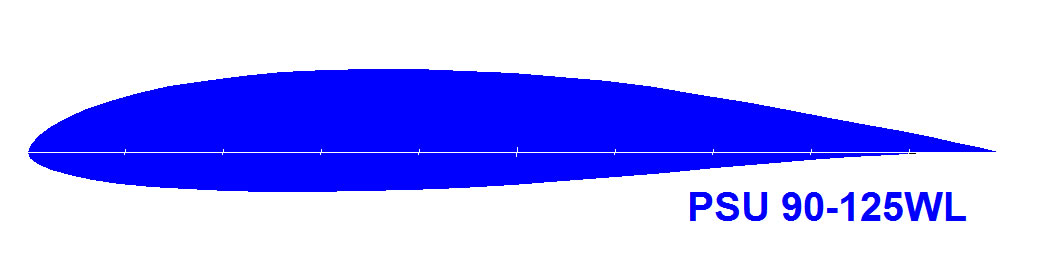
These design requirements are different than for a conventional sailplane airfoil. The resulting custom airfoil designed by Dr. Maughmer and Mr. Selig of Pennsylvania State University is shown in their figure below. Dr. Maughmer described the airfoil design philosophy as follows:
"The airfoil has the traditional undercamber removed from the lower surface trailing edge area, which minimizes the tendency to form detrimental laminar separation bubbles at low or negative angles of attack. At the price of a little Clmax which isn't important for a winglet anyway, the drag is lower than other sailplane airfoils everywhere up to CL =0.85, as well as at negative CL's, so that sideslips and horizontal gusts can be tolerated. The corners of the laminar bucket have been rounded to avoid unstable yawing moments that would be generated otherwise it the sailplane yawed to angles exceeding those corresponding to the sharp corners of the traditional Wortmann sailplane airfoils. Finally, the airfoil was designed to avoid laminar separation bubbles down to Re = 350,000."
WING AERODYNAMICS
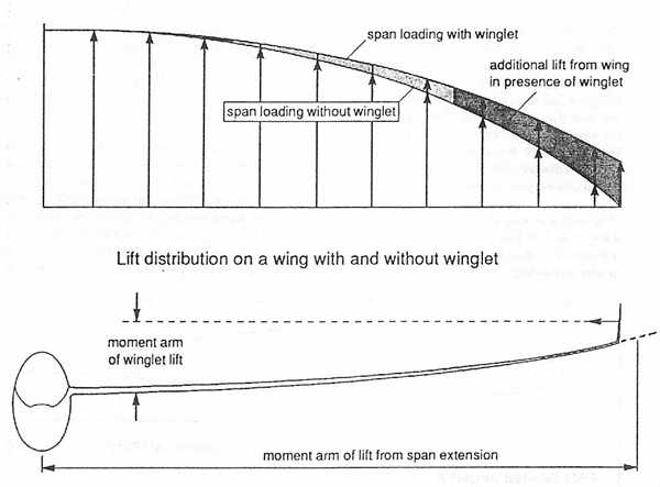
The change in the lift distribution of a wing with and without winglets is shown below. The boundary condition at the wingtip of the main wing no longer requires that the lift taper to zero at the tip. The assumed lift distribution for a wing with a winglet is assumed to terminate at an imaginary point equal to unfolding the vertical winglet in the horizontal plane. As a result the outer portion of the wing carries a higher load than it does without the winglet. Recent calculations on sailplanes with double trapezoidal platforms such as the ASW-20 or LS-6 suggest that this outer tip loading is more efficient from the standpoint of induced drag.
Secondly, the additional lift capability of the main wing means that the Clmax Of the overall wing is increased and the sailplanes circling performance will be enhanced.
Structural Loading
One of the key advantages of winglets is that they provide a performance increase
while only fractionally increasing the root bending moment on the spar compared
to a span extension. Whereas the moment arm of a span extension is one-halt
the semi-span of the wing (about 7.5 meter's), the moment arm of a winglet
is only equal to approximately one- half the vertical span (0.3 m) plus the
deflected wing elevation at the tip. For sailplanes, which are certified with
tip extensions, one can be assured that the winglet will not overload the
wing and all standard operating limitations will apply (Ventus, ASW-20, and
DG600).
FINAL DESIGN
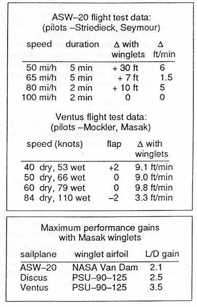
The final choice of design parameters is reflected in the design of the Ventus and ASW- 20 winglets, which have been highly successful in competition. The ASW-20 winglet went through two iterations and the Ventus, three, before it was concluded that the design had reached a high level of refinement.
FLIGHT TEST RESULTS
Competition Results
The response of pilots flying with winglets in competition has been very positive
overall. Certainly one of the measures of the success of the design is the
fact that pilots after a period of evaluation have chosen to fly with the
winglets. At the 1991 world contest in Uvalde, Texas, ten pilots chose to
fly with our winglets -- 8 Ventus, 1 ASW-20B, and 1 NimbusIII. At the end
of the contest, a Ventus flying with our winglets had won four of twelve contest
day and on the fastest day of the contest, the top five places in the 15 meter
class went to sailplanes flying with our winglets. Additionally the trophy
for the highest speed achieved overall went to Jan Anderson of Denmark, flying
a Ventus with our winglets (his speed also exceeded the highest achieved in
the Open Class.) Two weeks prior, at the 15 meter nationals in Hobbs, New
Mexico, Rheinhard Schramme from West Germany established an unofficial record
of sorts by flying his Ventus C around a closed course of greater than 500km
with an average speed of 171 km/h (he would have won were it not for a photo
penalty.)
Bruno Gantenbrink and Hemmann Hajek of West Germany chose to retrofit winglets to their Ventus-C's and were delighted with the handling and performance qualities that they observed. Mr. Hajek noted as a particular advantage the improvement in his ability to maintain constant bank angle and speed with a full load of water. With winglets the effective dihedral is increased and the sailplane can be banked steeper while retaining control.
The dolphining performance is naturally improved with the winglets since they act to reduce induced drag while pulling positive 'g's, and several pilots have perceived their sailplanes to have improved glide performance even at high cruising speeds in strong weather.
Flight Test Data
These positive results are confirmed by flight
tests based on three high tows with each sailplane type which show
the following performance gains as measured by the two-glider comparison technique.
CONCLUSIONS
The overall performance gains measured in free flight on sailplanes retrofitted with winglets are impressive and are supported by positive contest results. Handling qualities are improved in all cases, including improvement in roll rate and roll authority at high lift conditions.
The performance measurements have shown a higher gain in performance than would otherwise be predicted by conventional theory. It is believed that major benefits are derived from inhibiting the secondary flow that contaminates the boundary layer near the tip region. Prediction of this phenomenon requires computational power out of my grasp, and the present designs have been developed via experimentation and in-flight testing.
By August 1991, there were over forty-five sailplanes in the world flying with winglets designed and fabricated by the author. No negative reports or dangerous incidents (ie. flutter) of any kind have been reported. As a result of the positive service experience, DoT has recently issued a supplementary type certificate for flight with winglets on the Ventus model, using JAR-22 as a basis for compliance.